
- 1 ソリットモデリング_チュートリアル WHEEL_Nismo-LMGT4
- 1.1 1. Create a rim shape with a sketch
- 1.2 2. Rim shape solid
- 1.3 3. Create face design on surface
- 1.4 4. Cut the solid with face design
- 1.5 5. Make a solid that cuts the opening
- 1.6 6. Cut the rim of the solid that cuts the opening with the surface
- 1.7 7. Arrange the openings in a circular pattern
- 1.8 Make 8.5 holes
- 1.9 9. Weight reduction on the back side
- 1.10 10. Engraved NISMO logo
- 1.11 11. Completed Nismo-LMGT4
- 1.12 CATIA V5 Reference data with history
ソリットモデリング_チュートリアル WHEEL_Nismo-LMGT4
—-Command used —-
 sketch
 Wire frame (flat surface)
 Surface (shaft)
 Curve offset (parallel curve)
 Sketch-based feature (shaft)
 Surface-based feature (split)
 Sketch-based feature (pad)
 Boolean operations (difference)
 Transform feature (circular pattern)
 Dress-up feature (draft)
 Dress-up feature (edge fillet)
We will create the wheel shape using the basic solid tools of CATIA V5.
Basic way to make a wheel
- Rim basic shape
- Face design side
- Aperture
- Mounting holes
Basically, it is recommended to cut from the Rim shape.
Forged wheels are made by cutting, so the shape can be reproduced by making it in the cutting process.
There are some shapes that can be made together by sketching the rim, but since it is composed of multiple solids, it is
a practice to create parts using CATIA’s multi-body.
It is composed of surface + solid, but it can also be made using the shaft of solid.
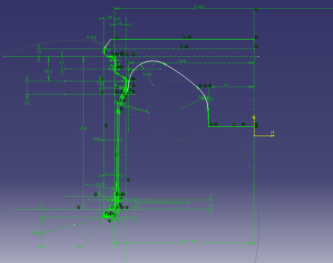
1. Create a rim shape with a sketch
The basic conditions of Rim are similar to the standard such as external dimensions and flange shape.
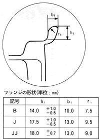
The fine shape will vary depending on the inch, but it should be good to some extent. Because it’s a model
![]() sketch
sketch
Click here for a sketch of the 18inch reference rim shape
Make the design part a buried shape.
The shape of the back side is a temporary shape because it will be changed later according to the design side.
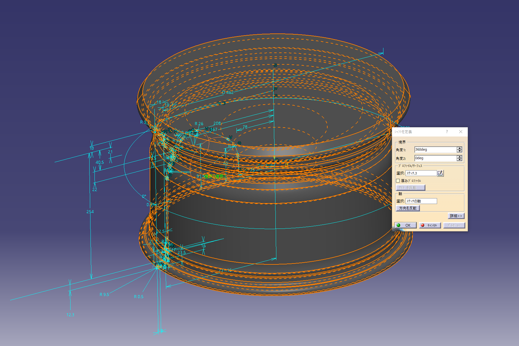
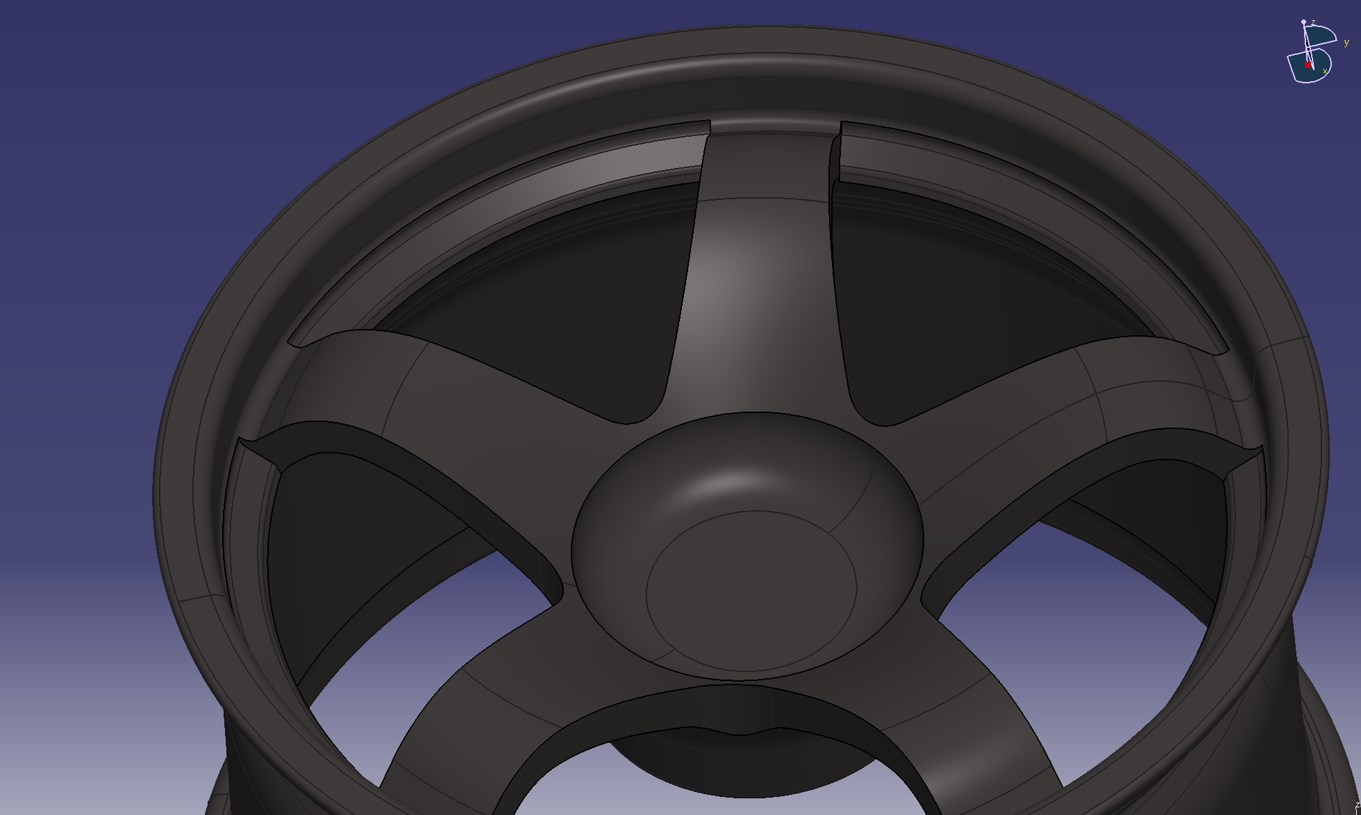
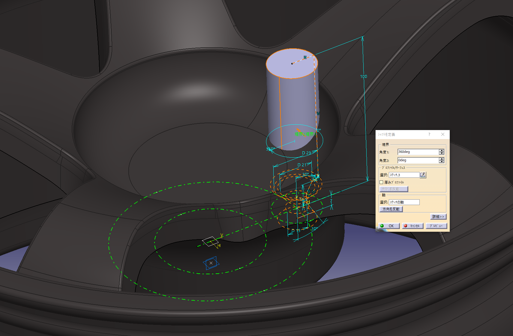
2. Rim shape solid
Solidify the sketch with a shaft.
![]() Sketch-based feature (shaft)
Sketch-based feature (shaft)
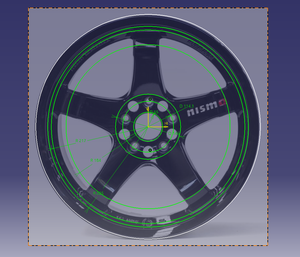
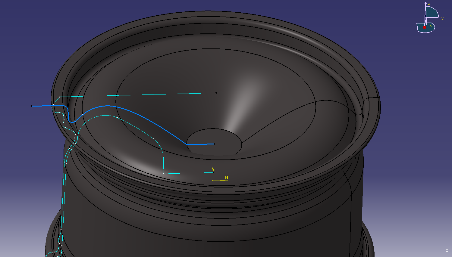
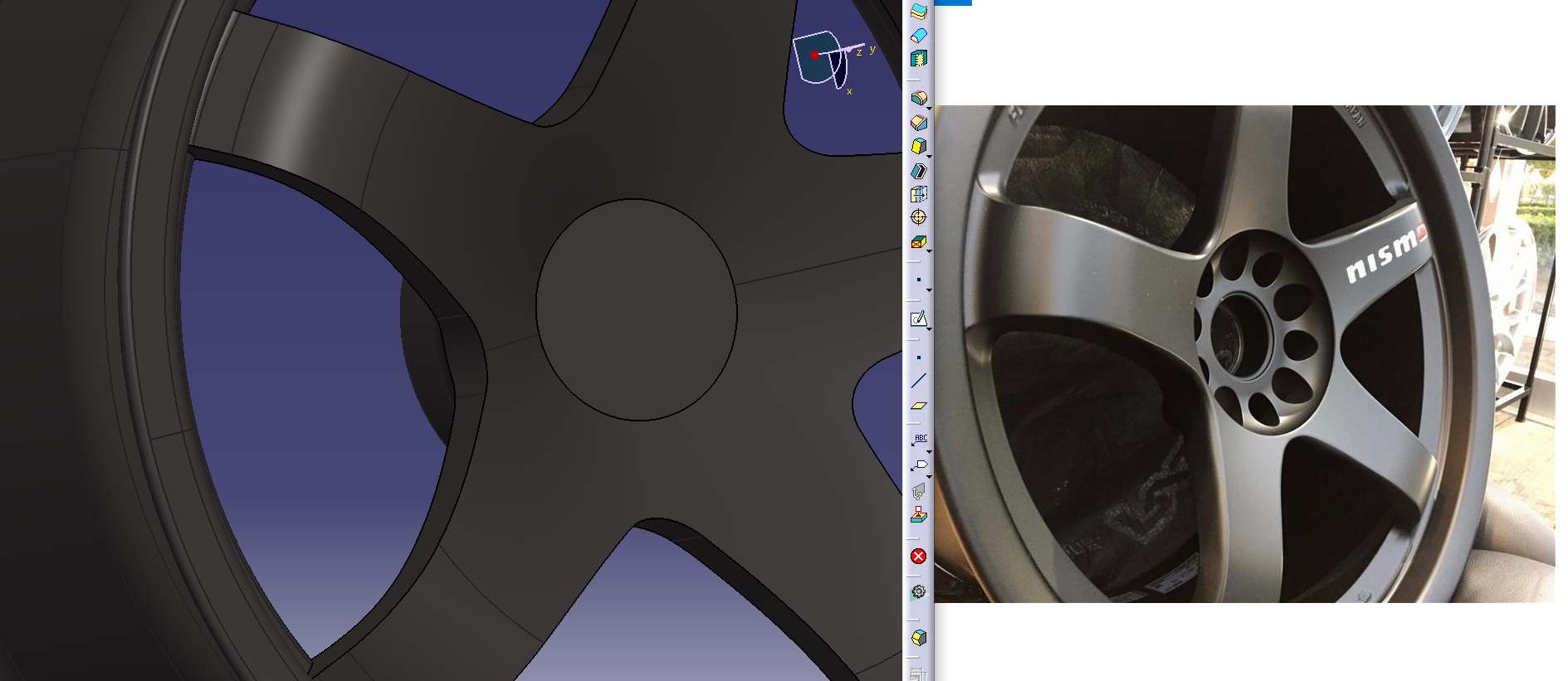
3. Create face design on surface
Place the photo
Click here for the placement method ⇒ Want to trace the CATIA design sketch? Disclosure of tricks
Click here for image data ⇒ 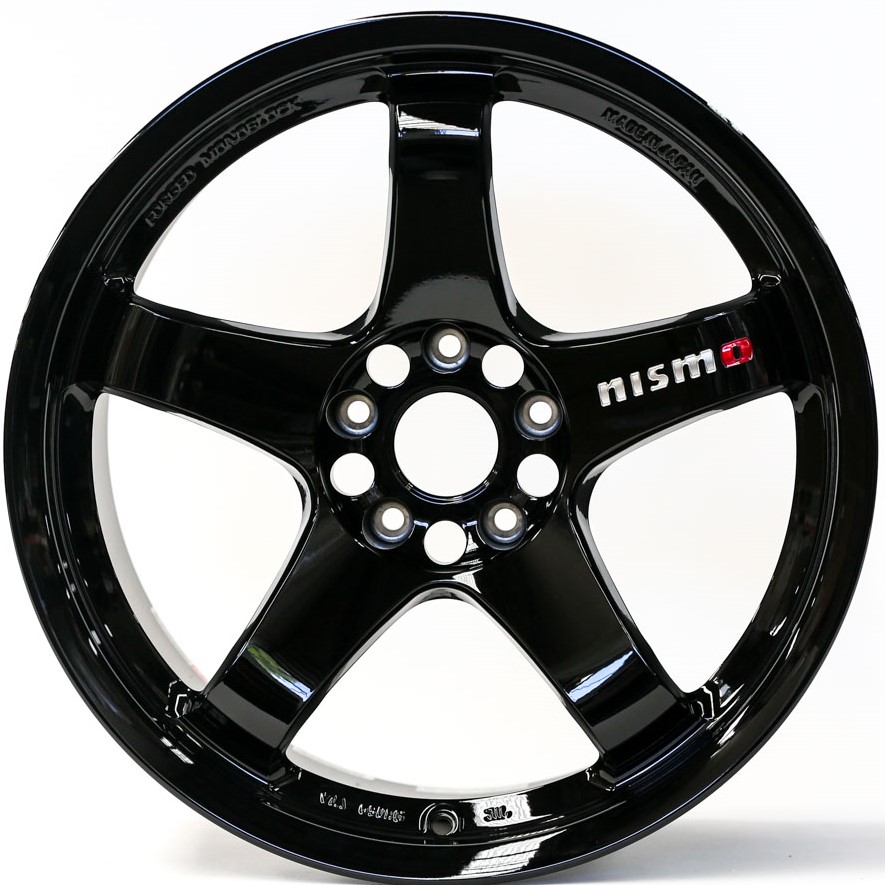
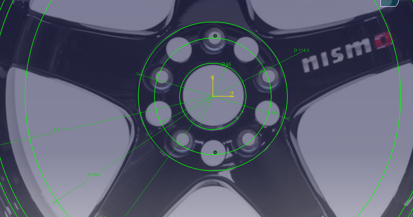
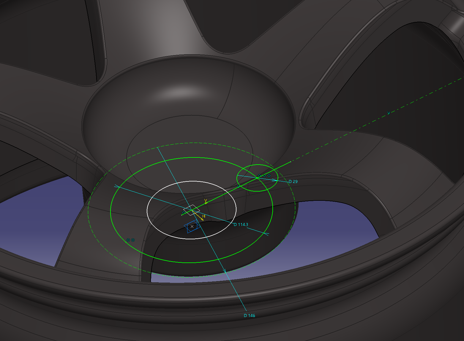
Adjust the photo based on the fixed dimensions such as the mounting holes. Since the
PCD is 114.3., Make a sketch of a circle of φ114.3 and fine-tune the scaling.
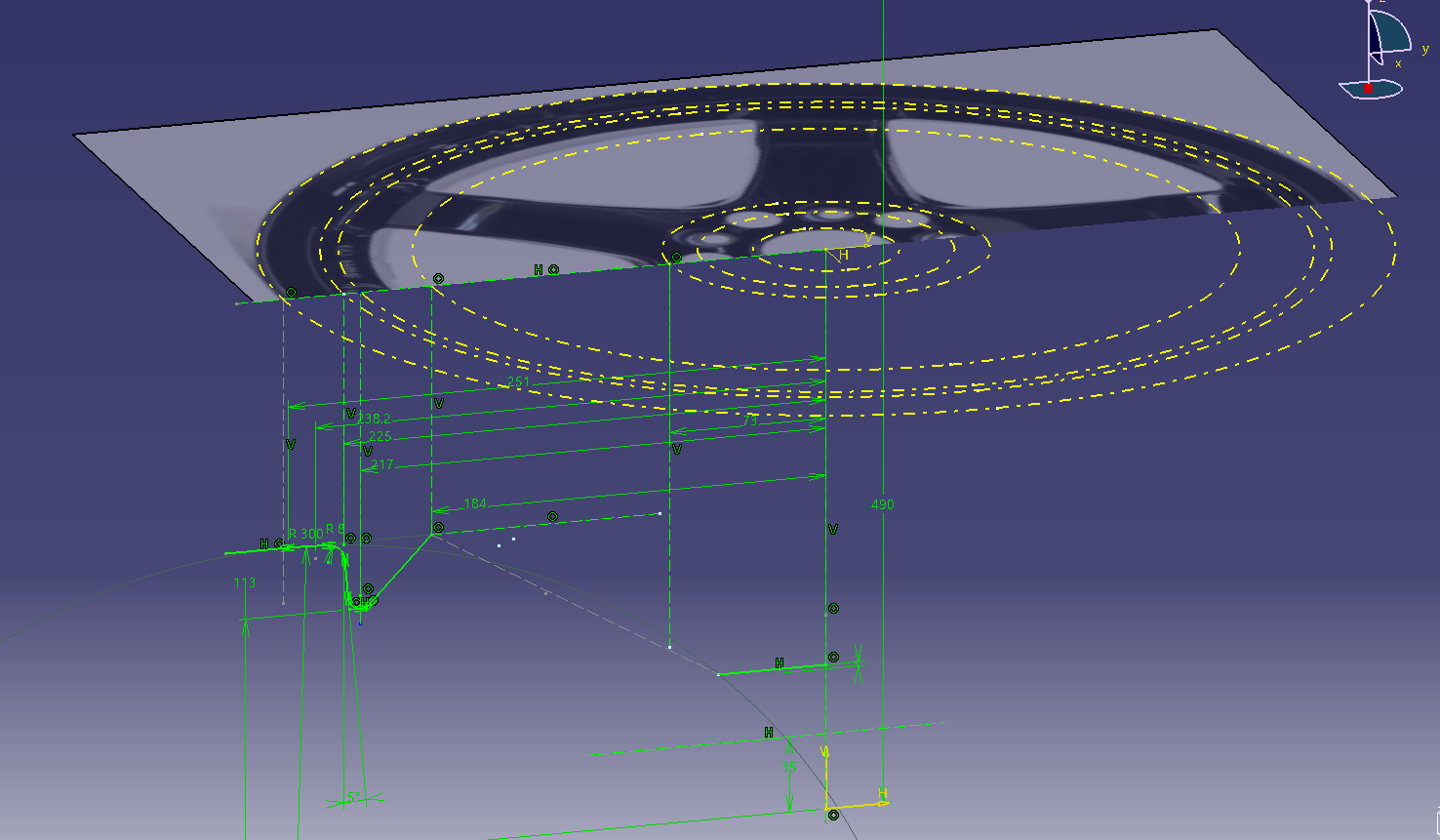
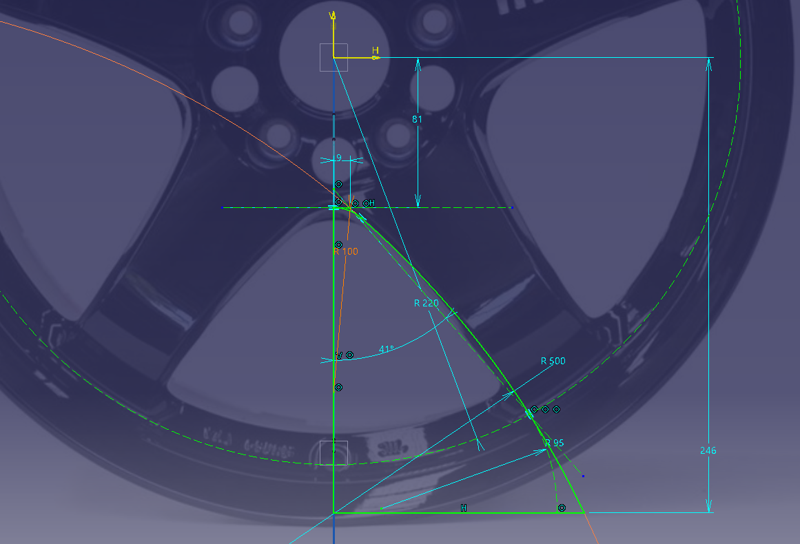
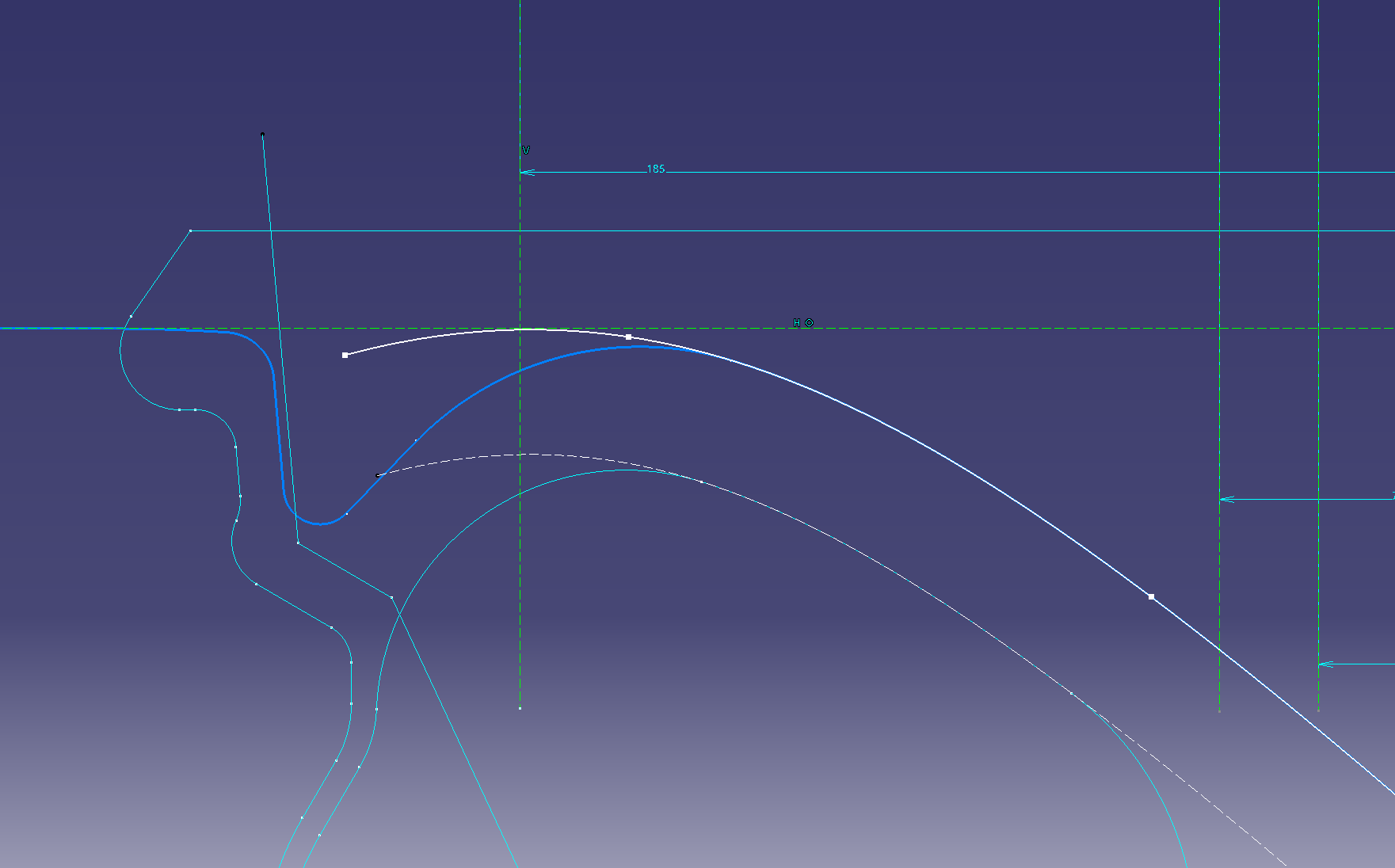
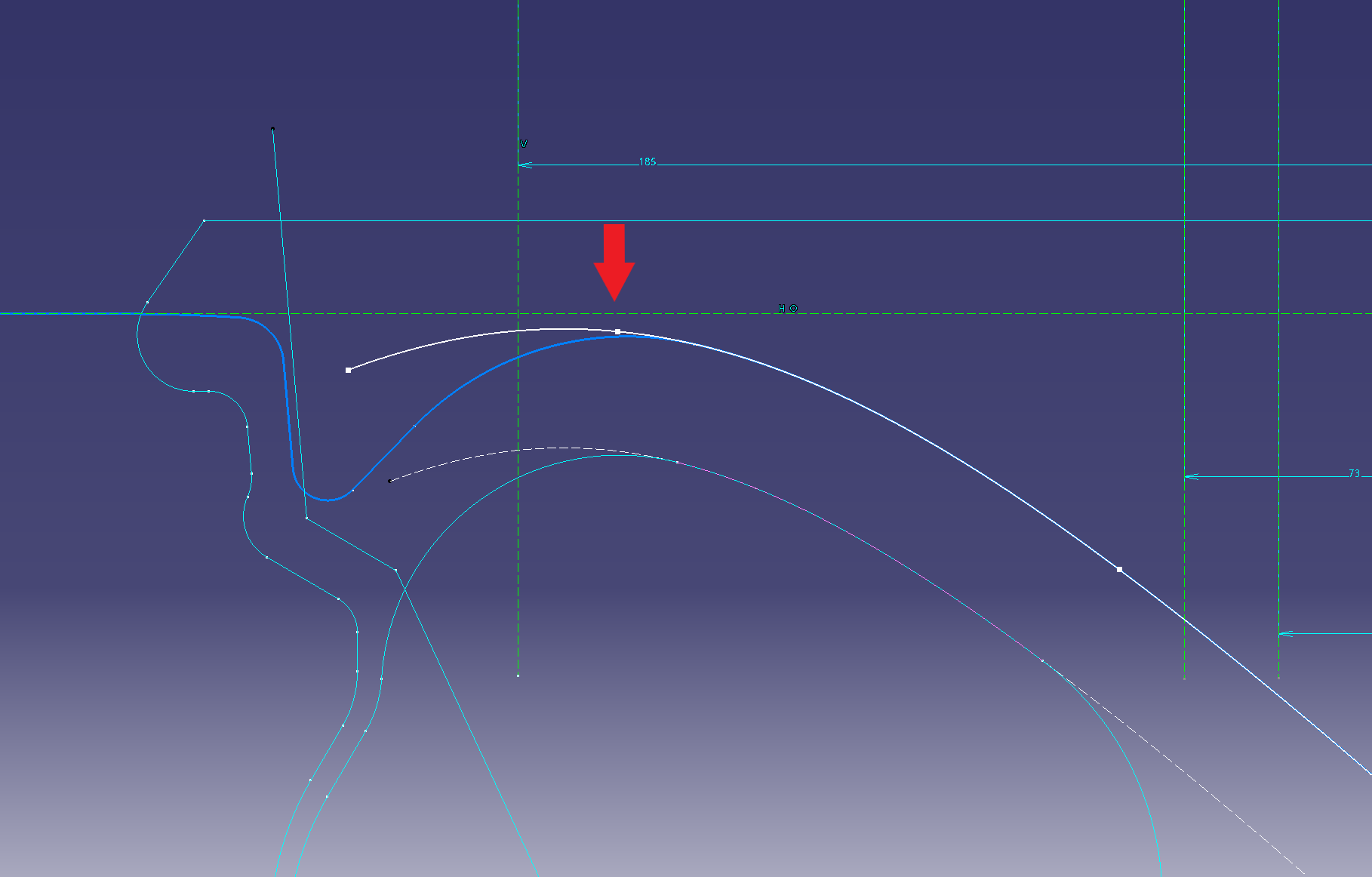
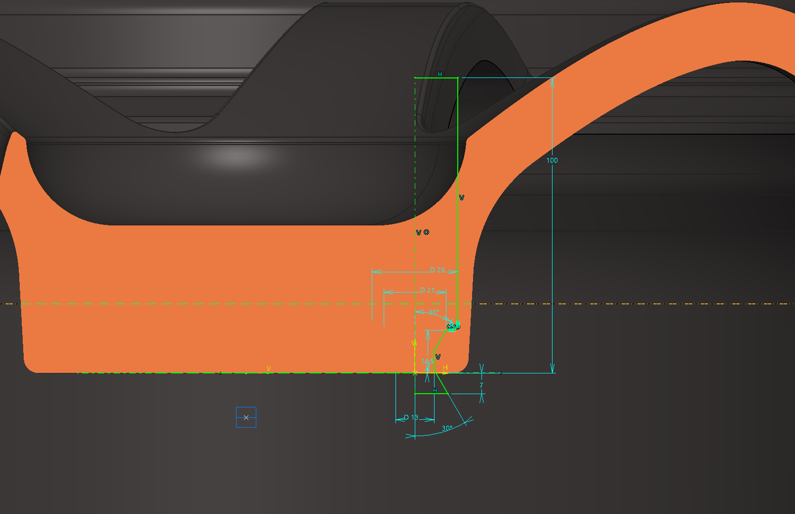
Determine the basic cross section of the wheel
Sketch on the XZ plane in the cross-section direction
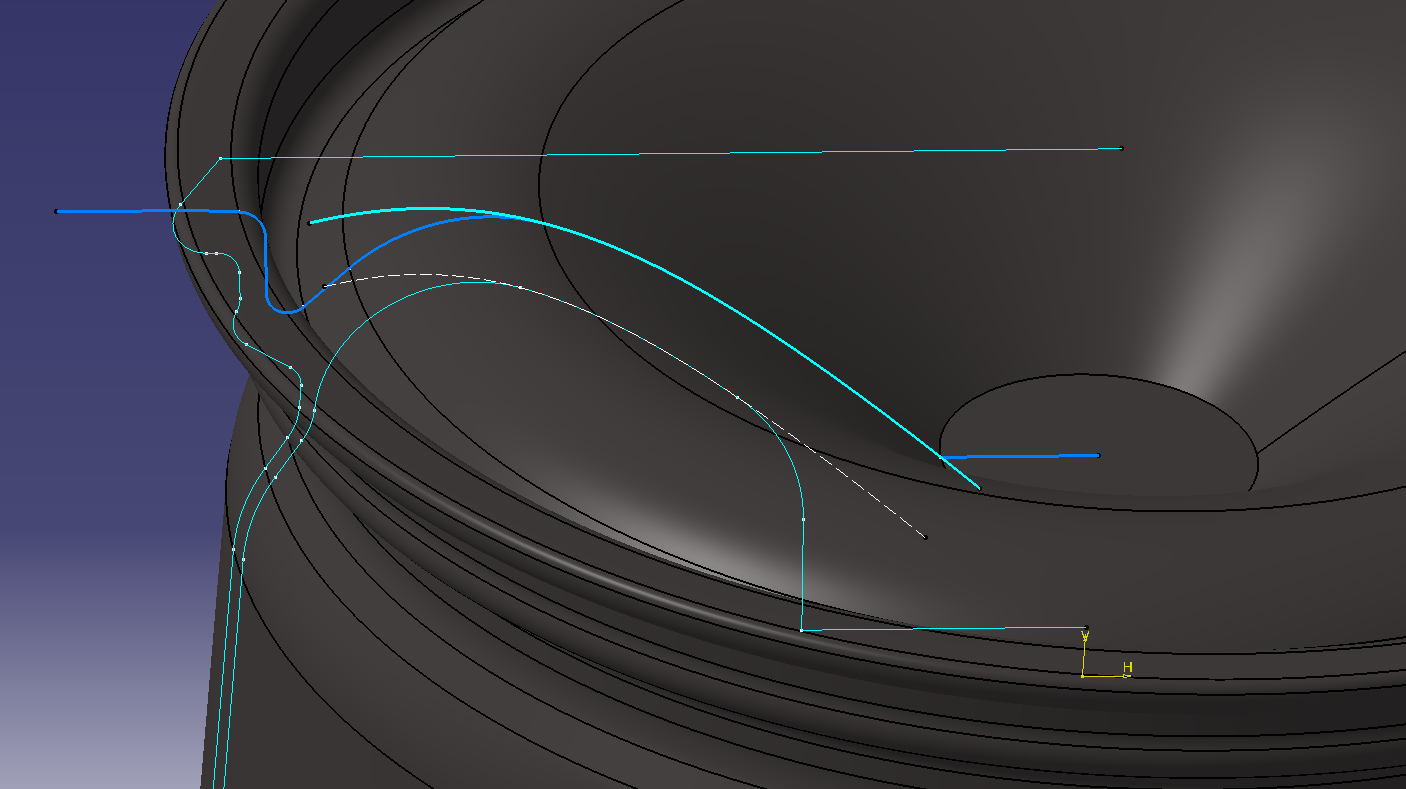
Read the design shape of the face while looking at the highlights in the photo.
Draw the position of the cross section according to the apex of R determined in the photograph from the front.
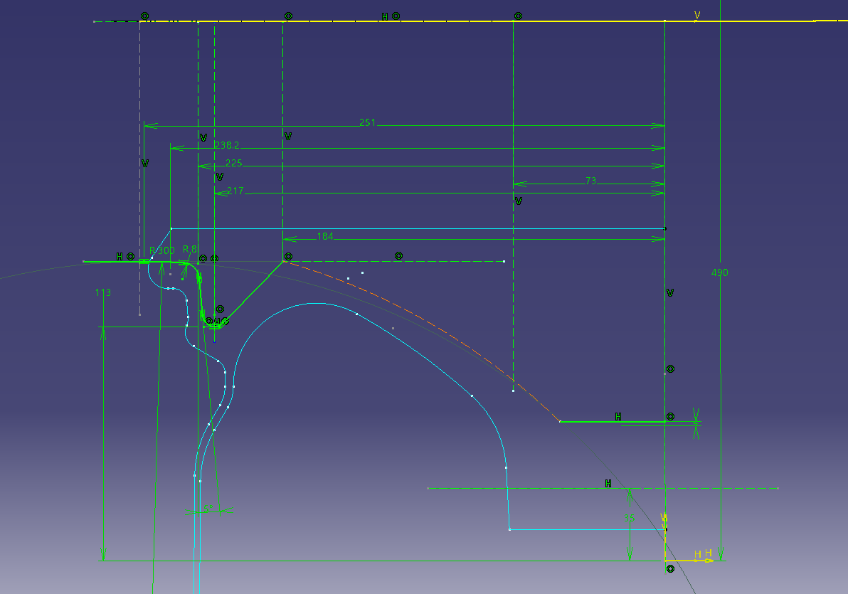
You can draw with a sketch as it
is, but this time I will make a design curve using splines.
Sketch ① = (cross section sketch blue)
Sketch ② = (spline)
Make a curve with a spline on the new sketch (sketch ②) (blue is the sketch ① made earlier)
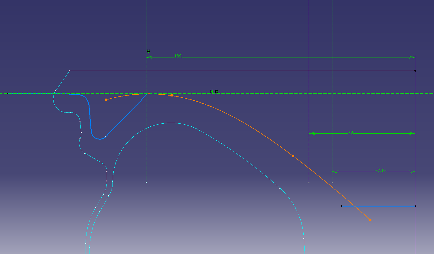
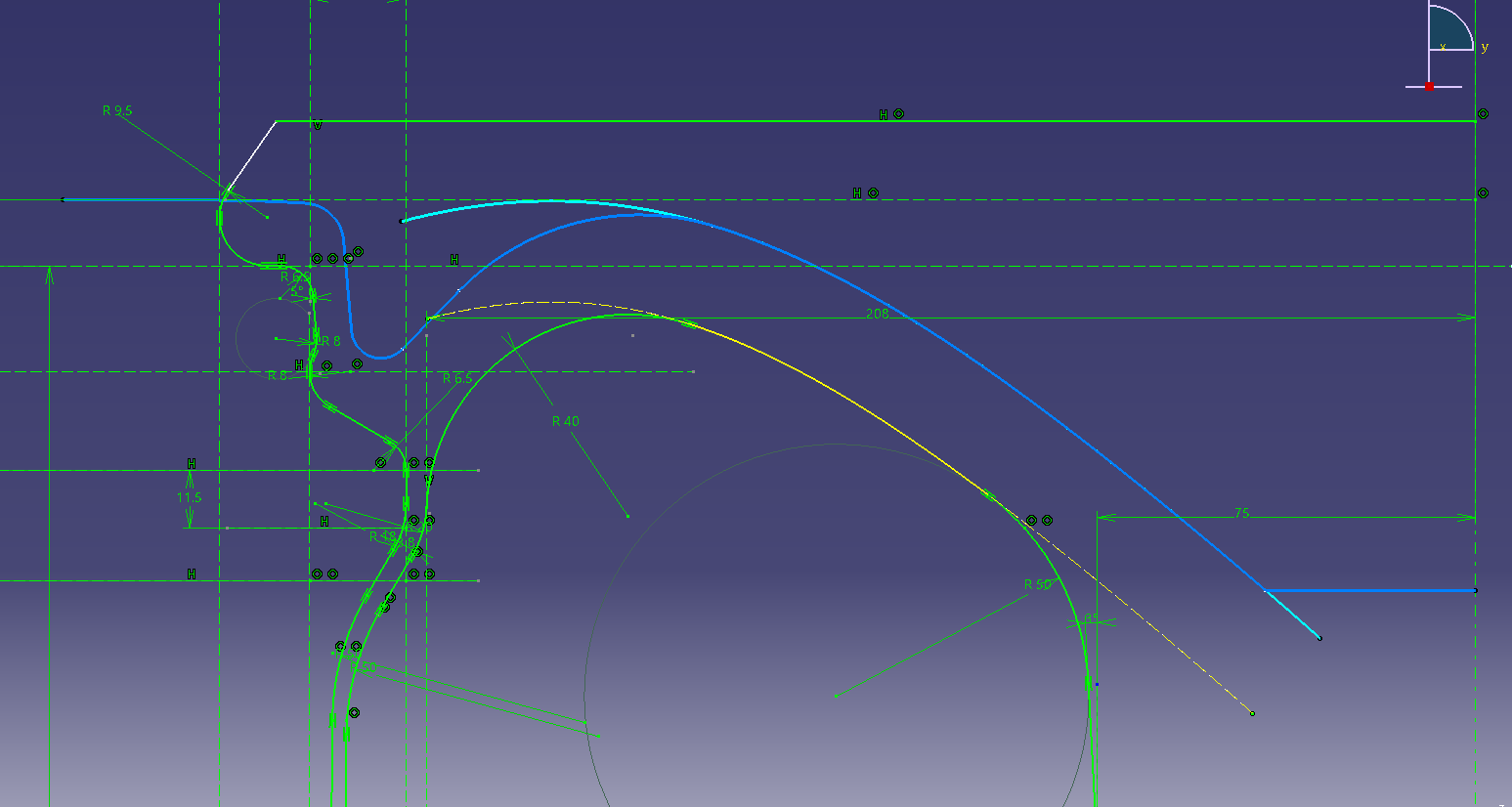
Link the sketch of the spline and the sketch of the face cross section
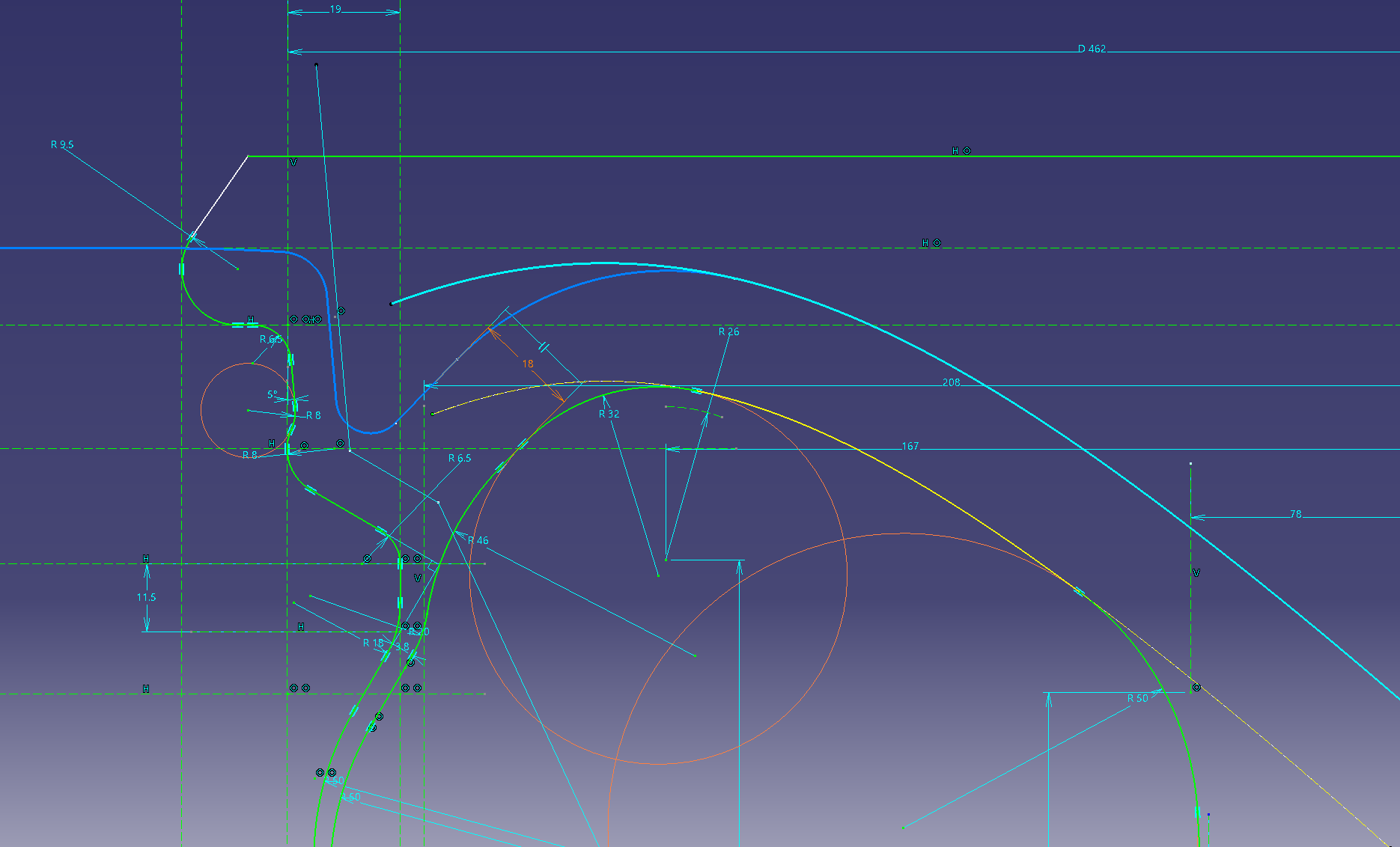
Project the spline of (Sketch ②) onto (Sketch ①).
Let’s leave the projected link as it is.
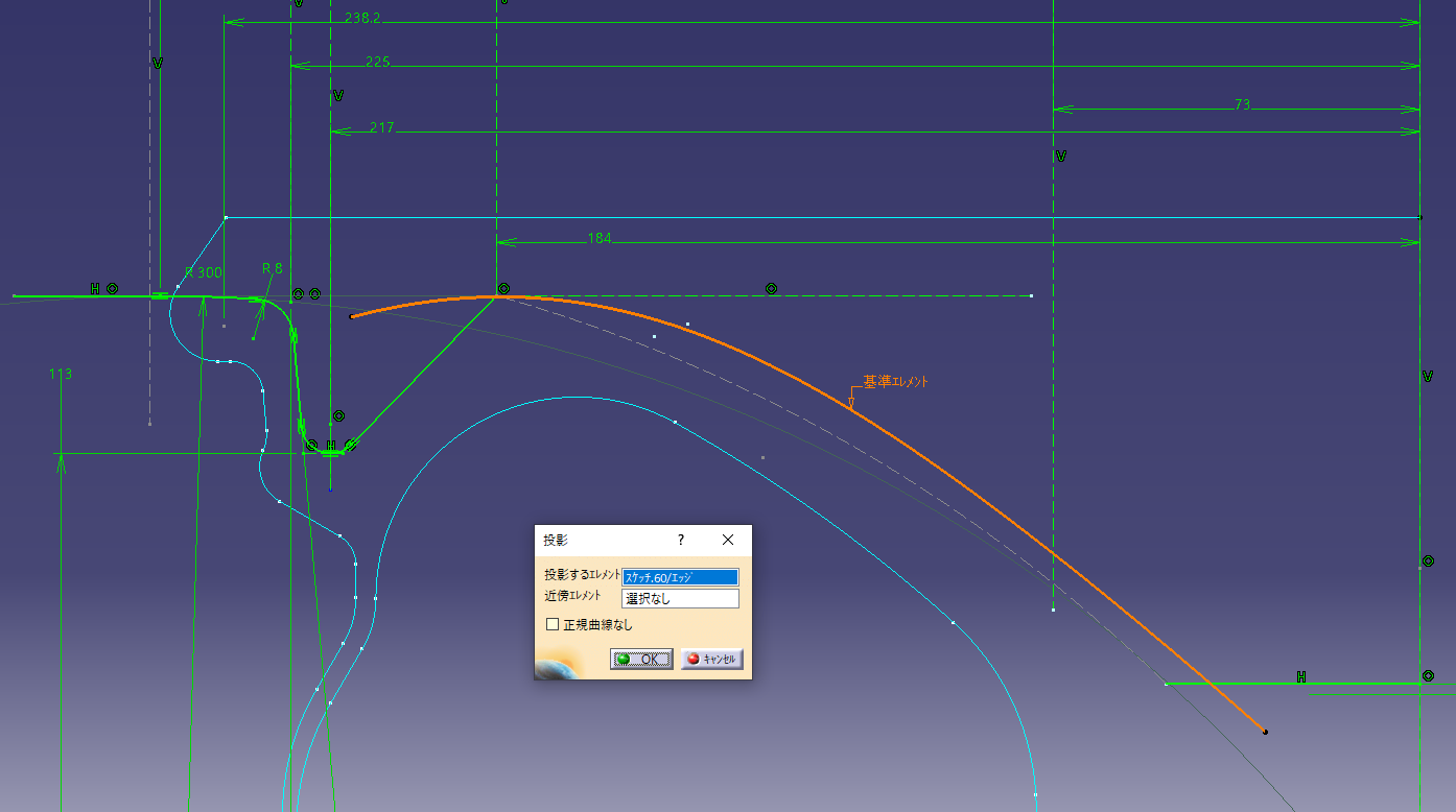
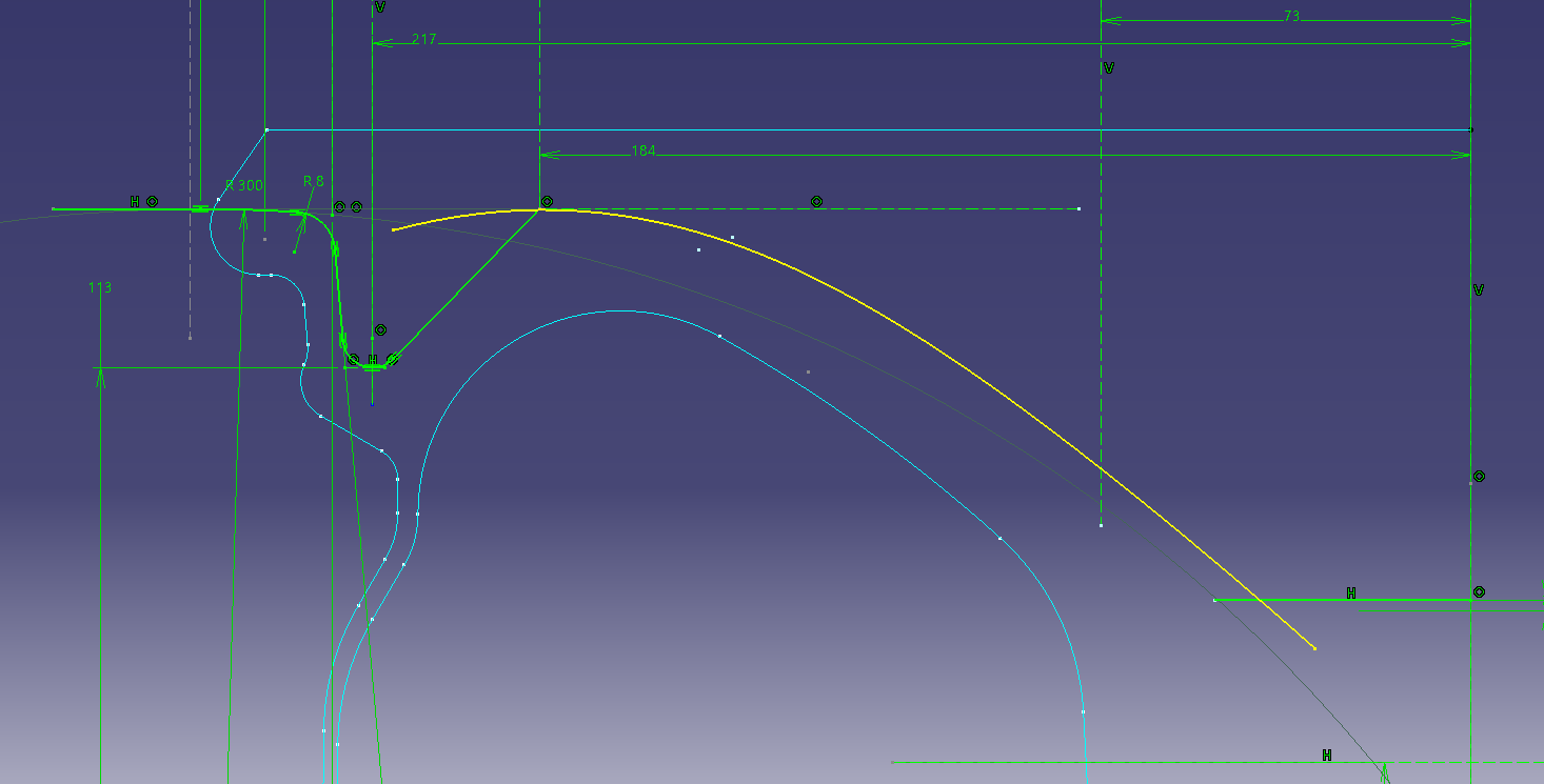
If it is a yellow line, it is linked.
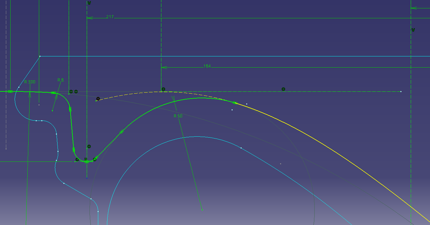
Put a fillet in the projection line and connect it. (R50)
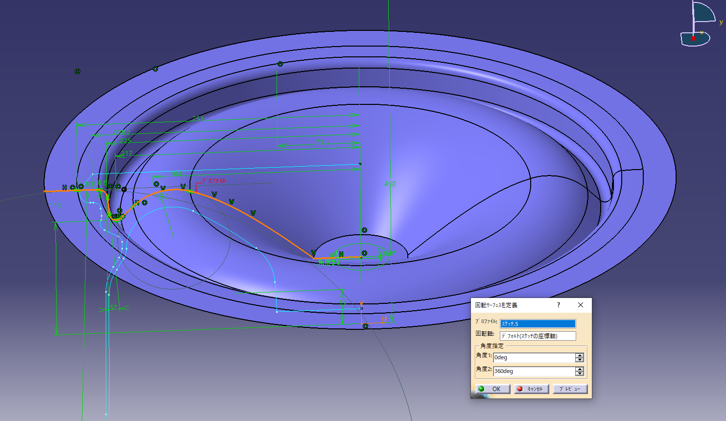
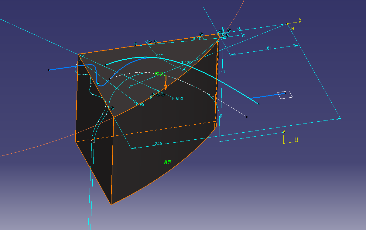
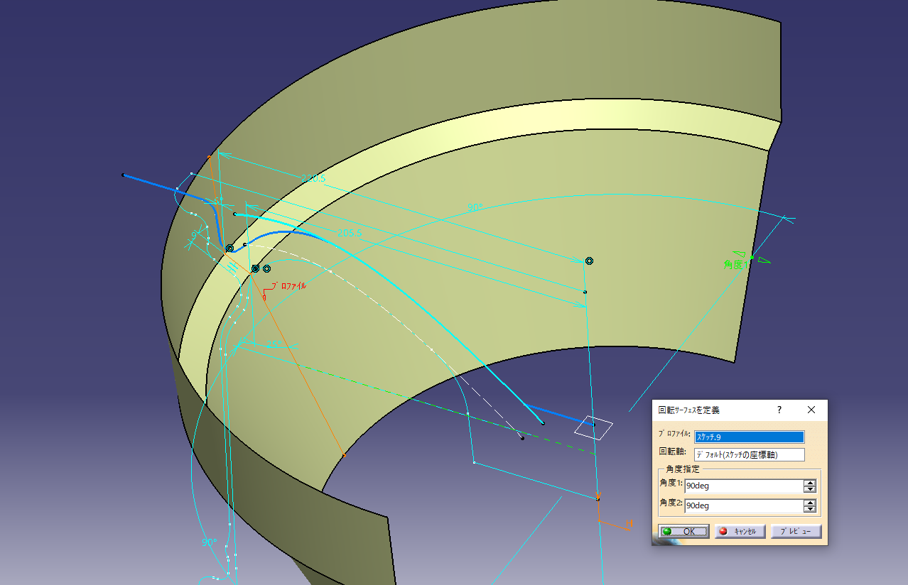
Create a rotating surface on the surface (shaft).
![]() Surface (shaft)
Surface (shaft)
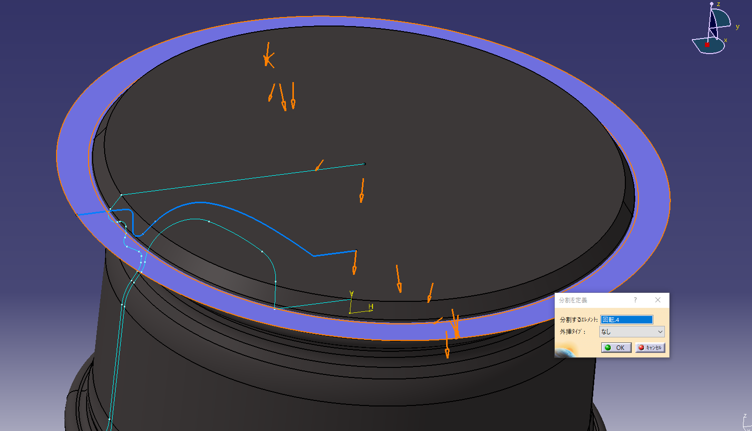
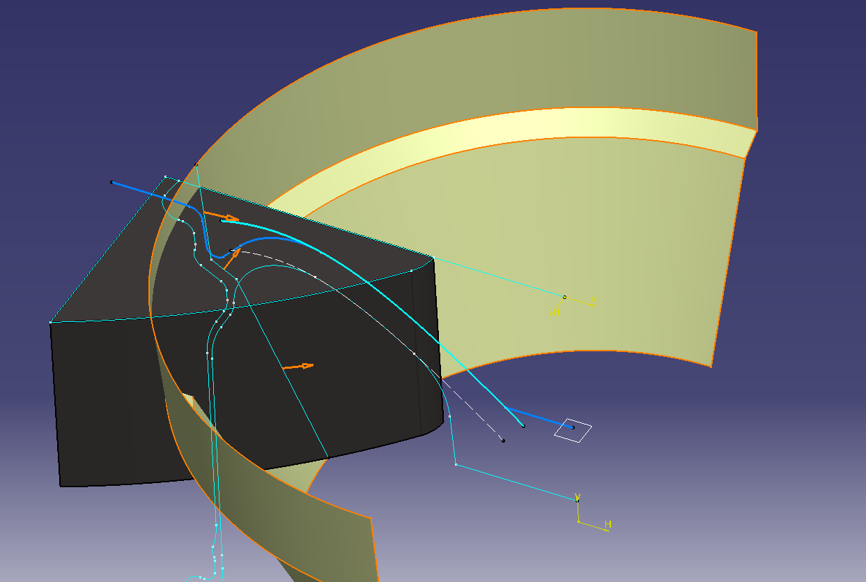
4. Cut the solid with face design
Cut the rim solid using the surface.
![]() Surface-based feature (split)
Surface-based feature (split)
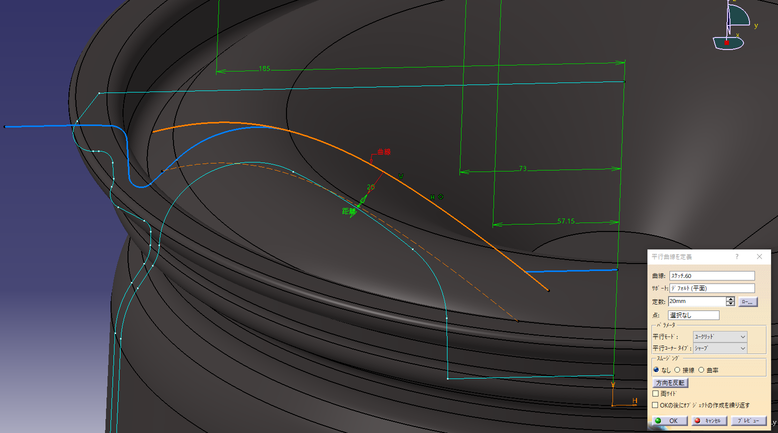
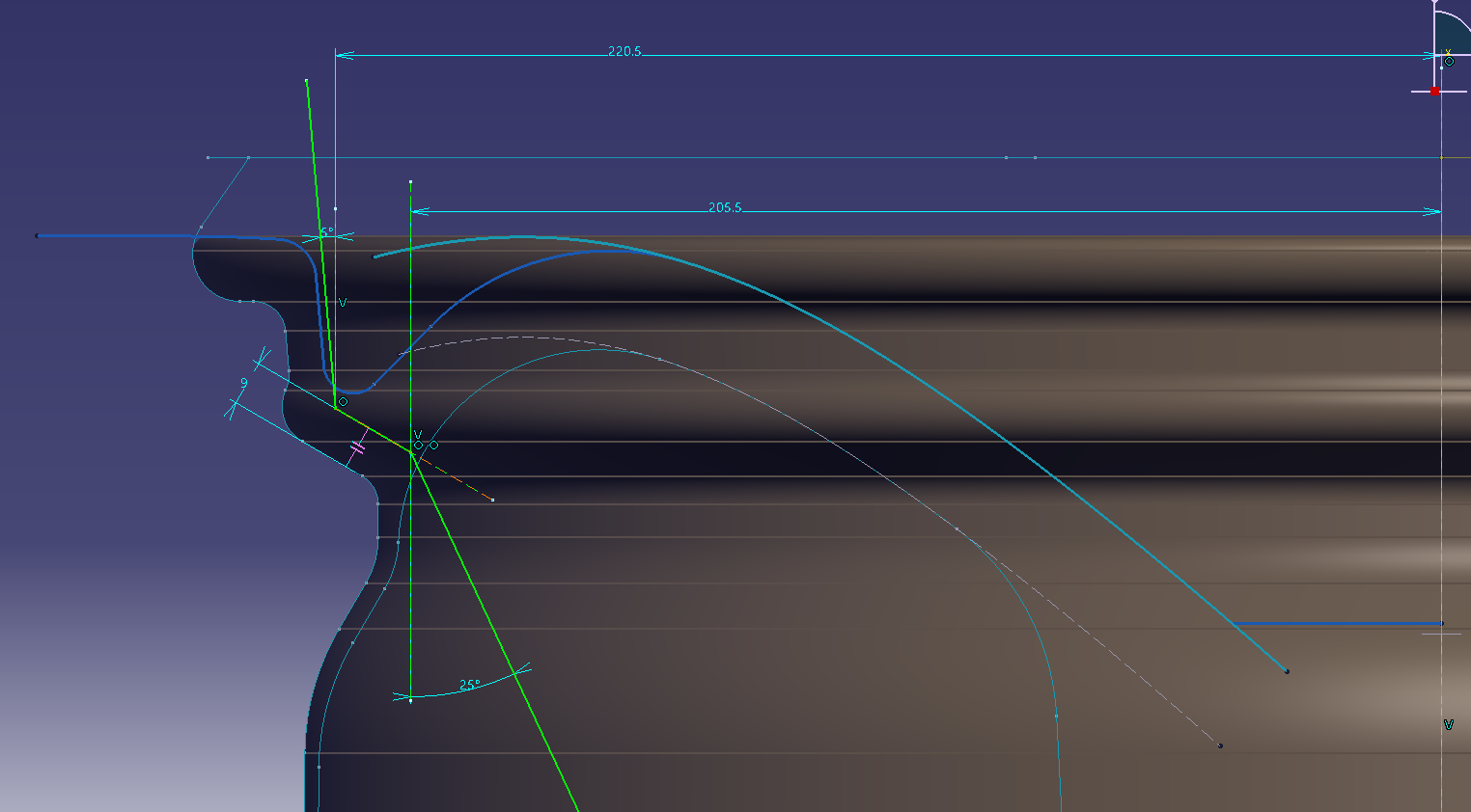
I want to make the back side of the basic shape of Rim created earlier parallel to the spline, so I
will make an offset curve of the spline shape. (Offset 20)
Project and change the rim shape sketch.
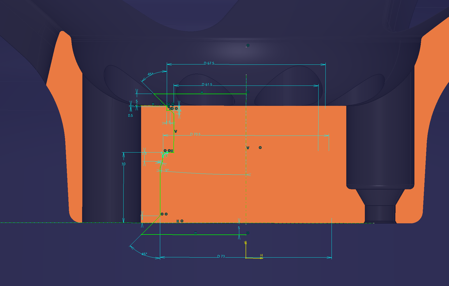
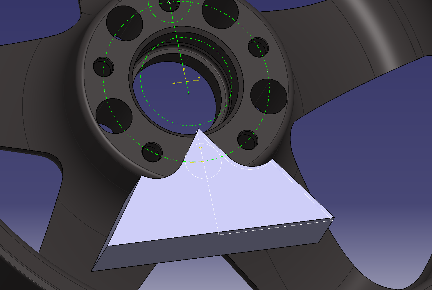
5. Make a solid that cuts the opening
Draw the opening in a sketch.
Since it is a symmetrical shape, draw half.
Let’s restrain it so that it can be adjusted.
Make it a solid with a pad
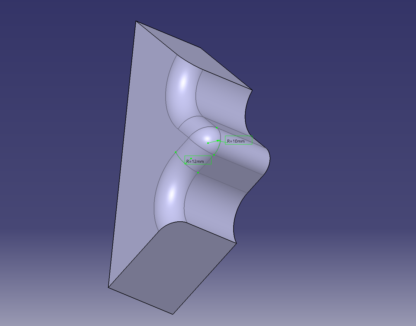
6. Cut the rim of the solid that cuts the opening with the surface
Make a cross section that cuts the outer circumference of the opening
Divide by surface.
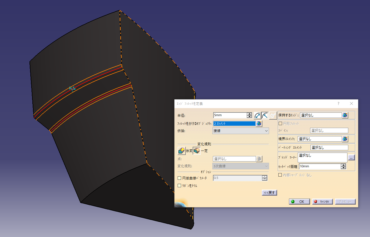
Put the fillet
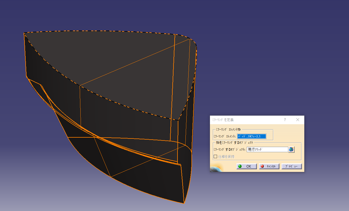
Mirroring completes one opening
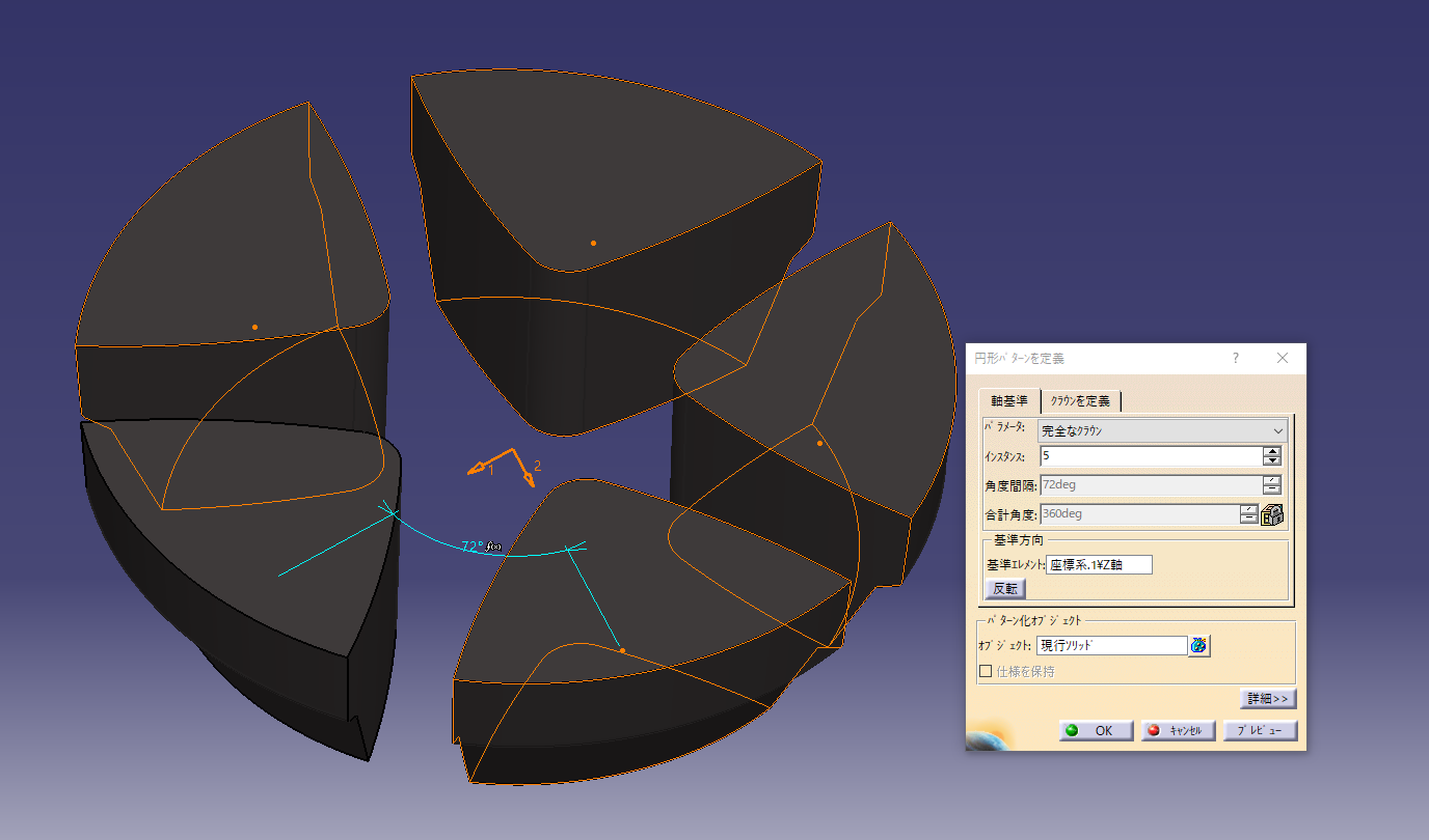
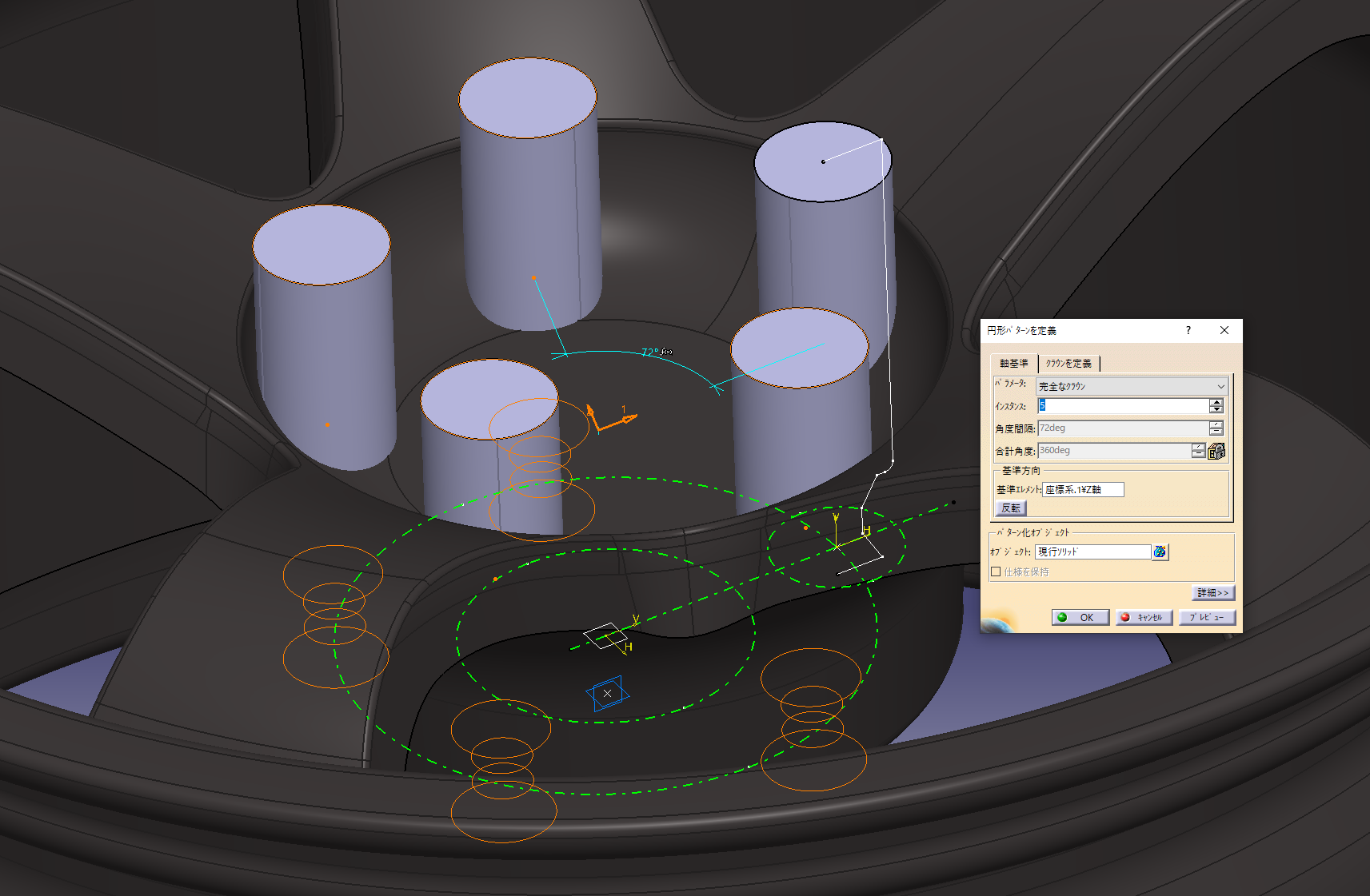
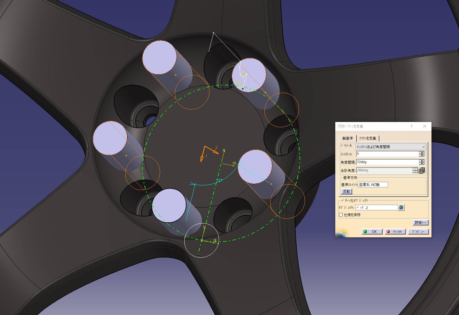
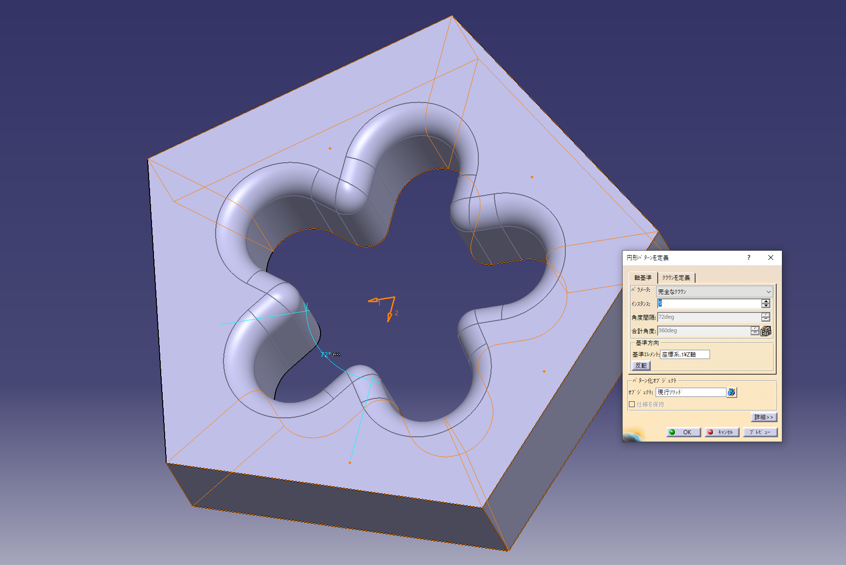
7. Arrange the openings in a circular pattern
Center axis (Z axis) + perfect crown + instance 5 and evenly distribute 5 pieces on the circumference
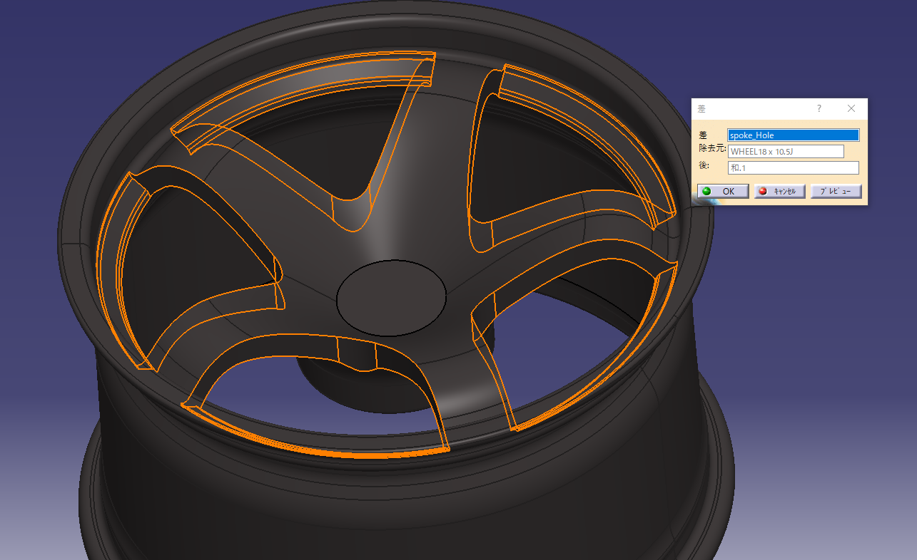
Make a hole in the rim shape and check the design.
Command used: Boolean operation (difference)
Added central dent
The image has been completed
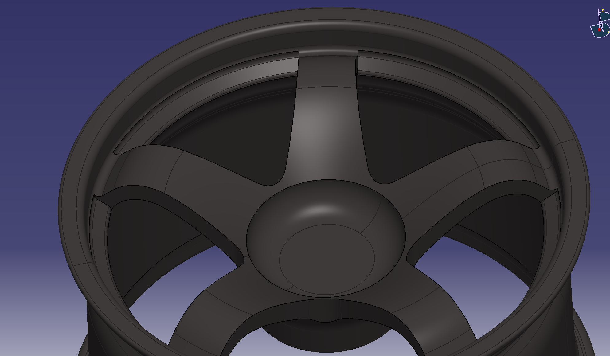
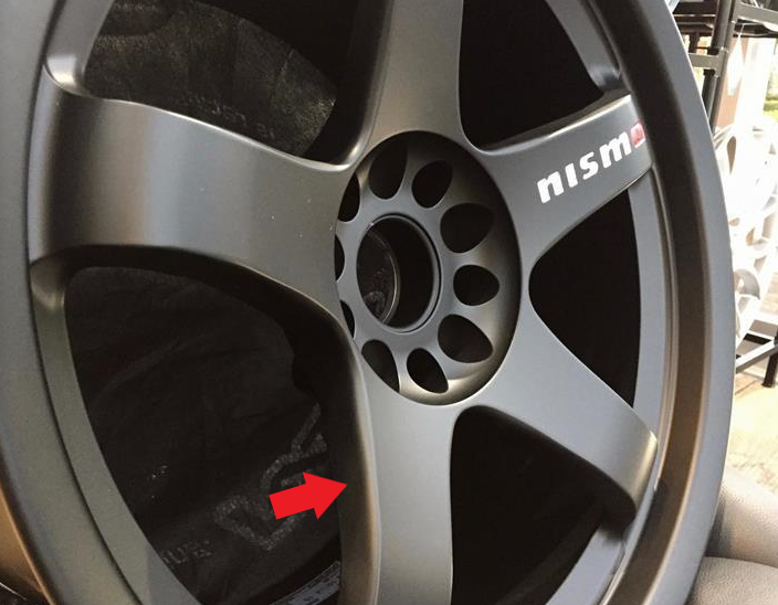
Adjust while comparing with the photo.
If you have a photo from an angle, you can compare the shape of the solid, so adjust it by comparing it with multiple images.
The R of the spokes feels tight, so adjust it.
I lowered the apex of R a little
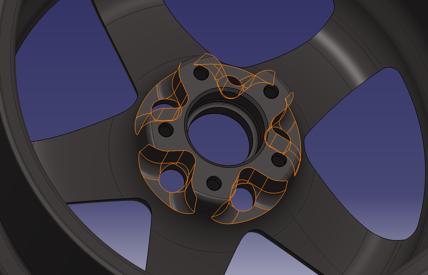
Change the back shape of the rim to match the face surface
Add a gradient to the side of the hole
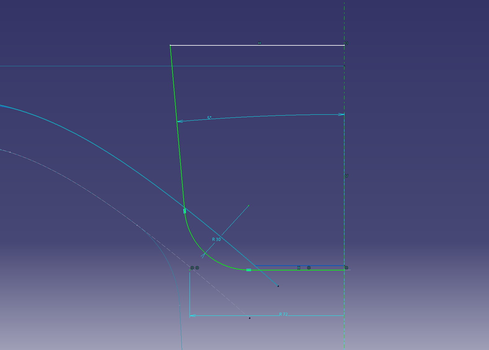
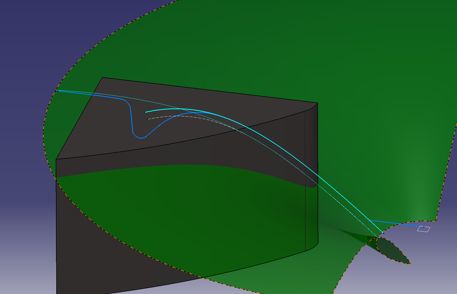
Make a reference line to add a gradient Make
a parallel line of splines on the face surface (6 mm offset)
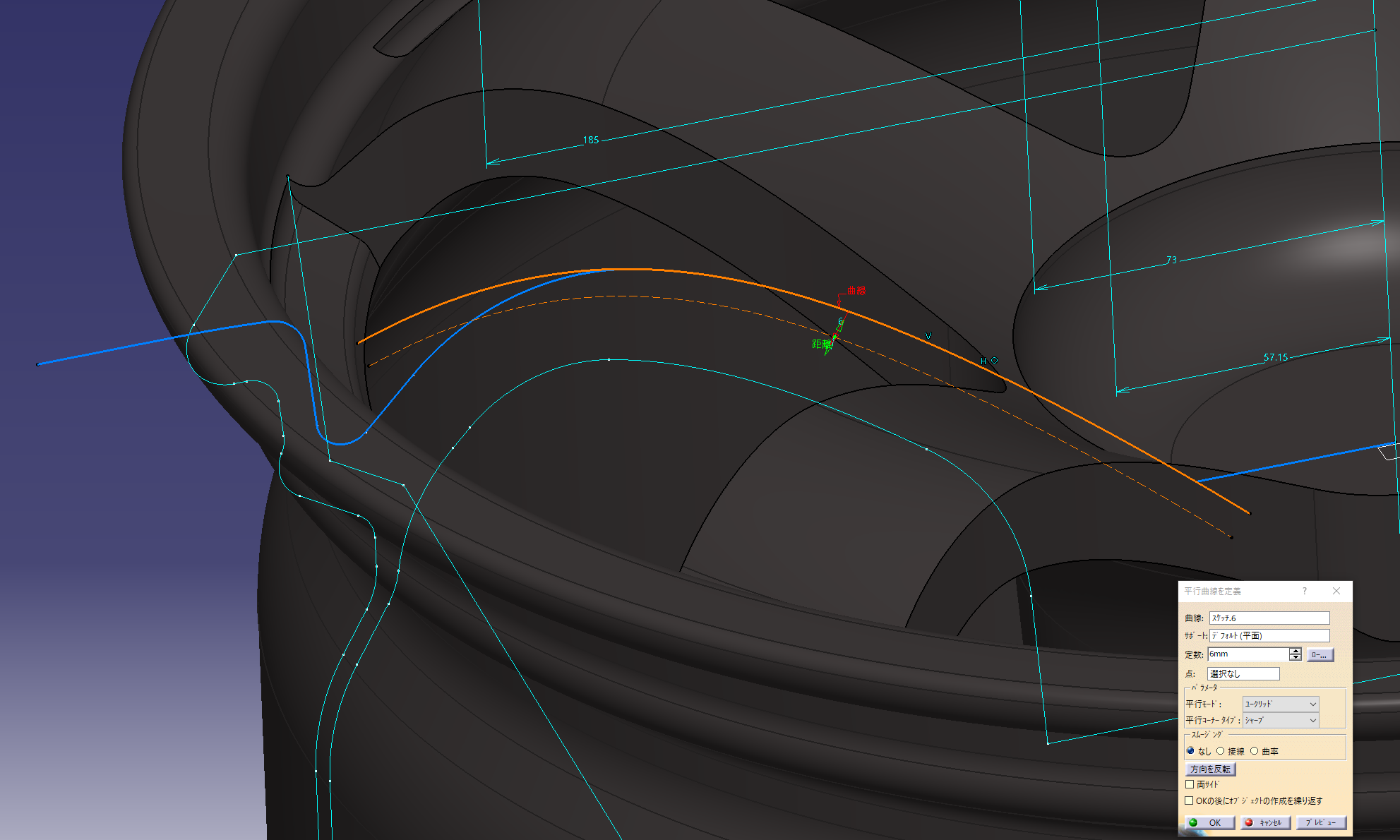
Make a spline while matching the projected parallel lines
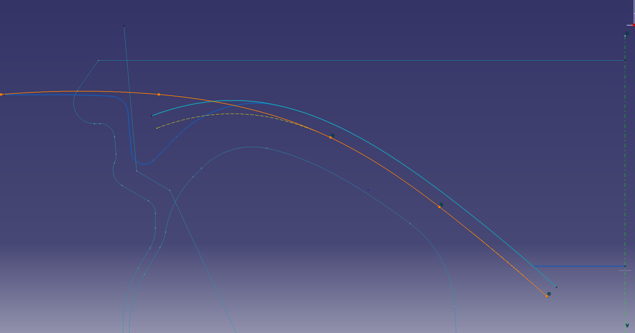
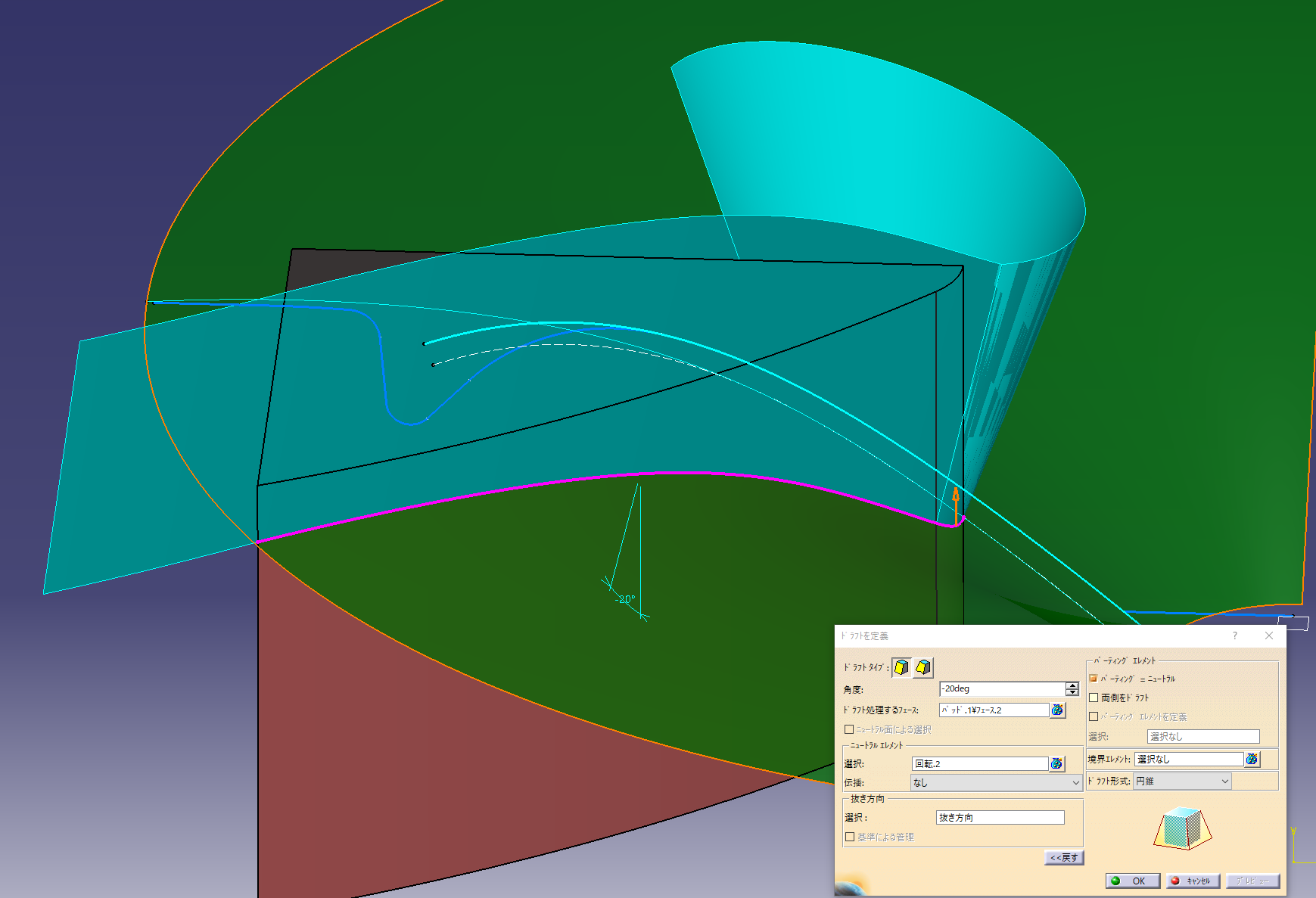
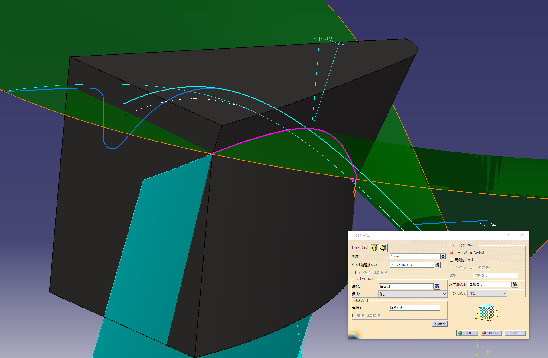
Make a slope-based surface
Select on the parting element to add the gradient up or down
Added a fillet with an arc length of 5 mm
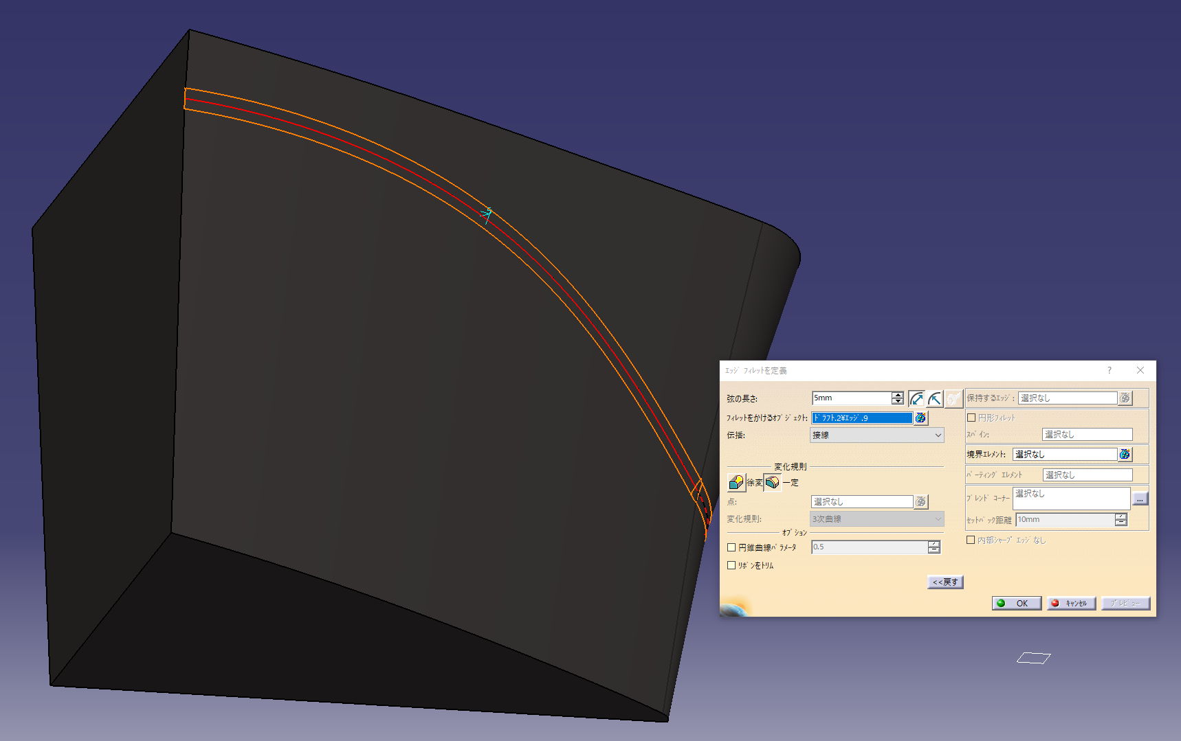
Added 18 mm length of vertical fillet arc
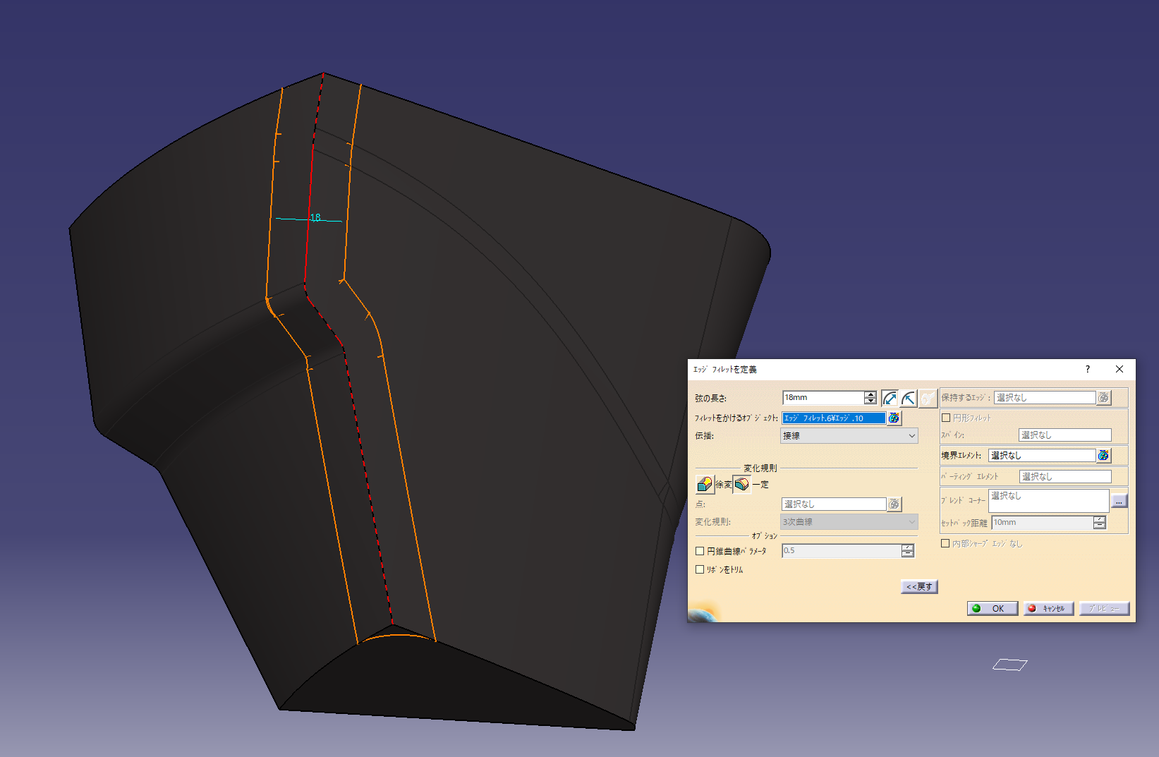
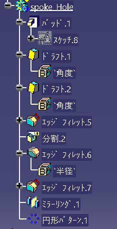
The history tree looks like this
Update and check the image
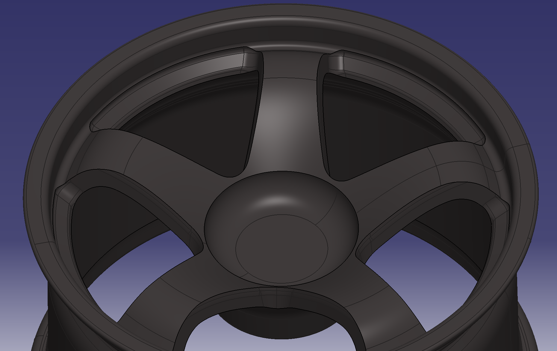
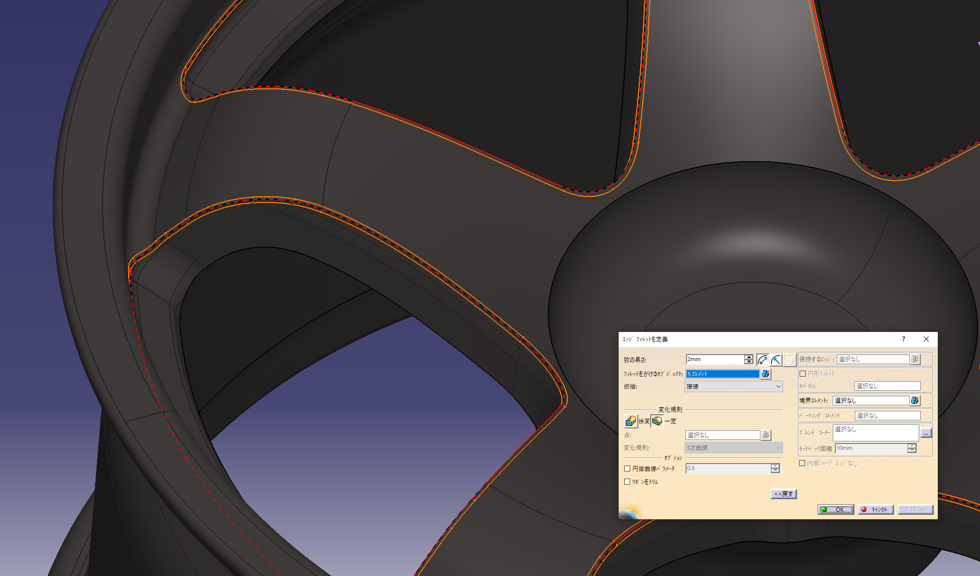
Added a fillet with an arc length of 2 mm
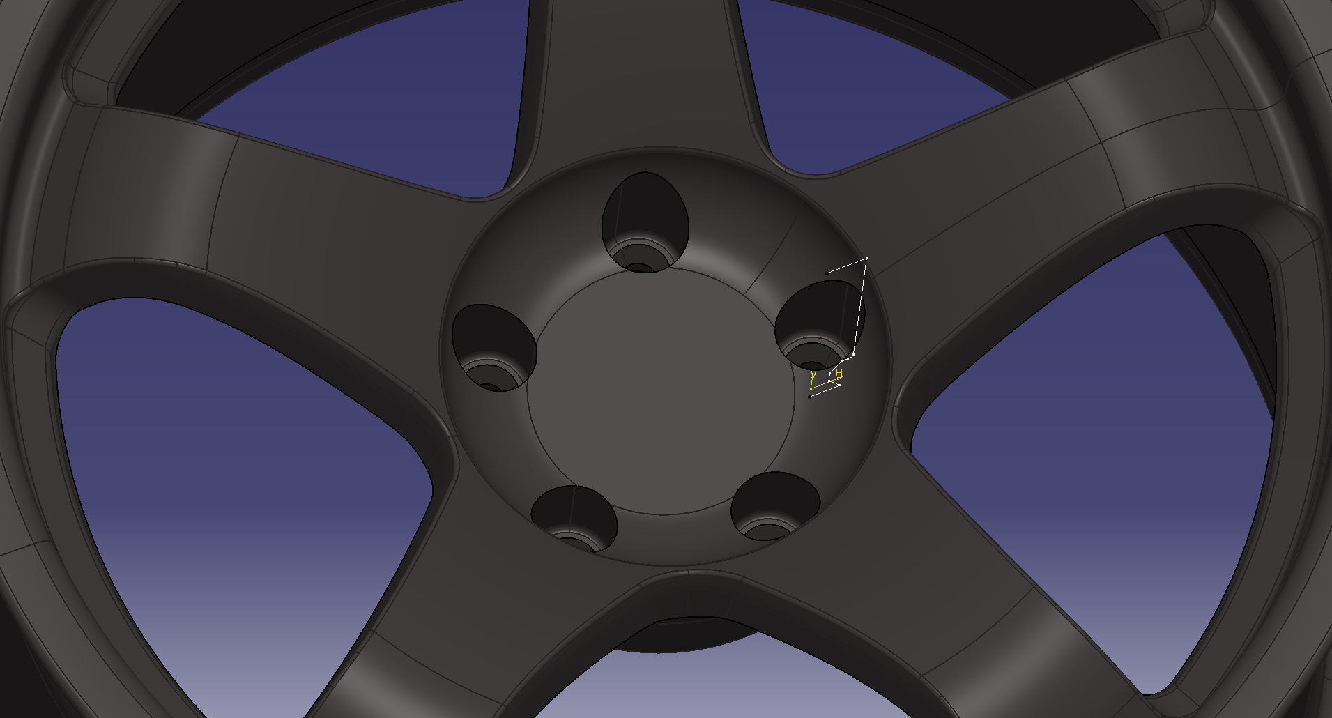
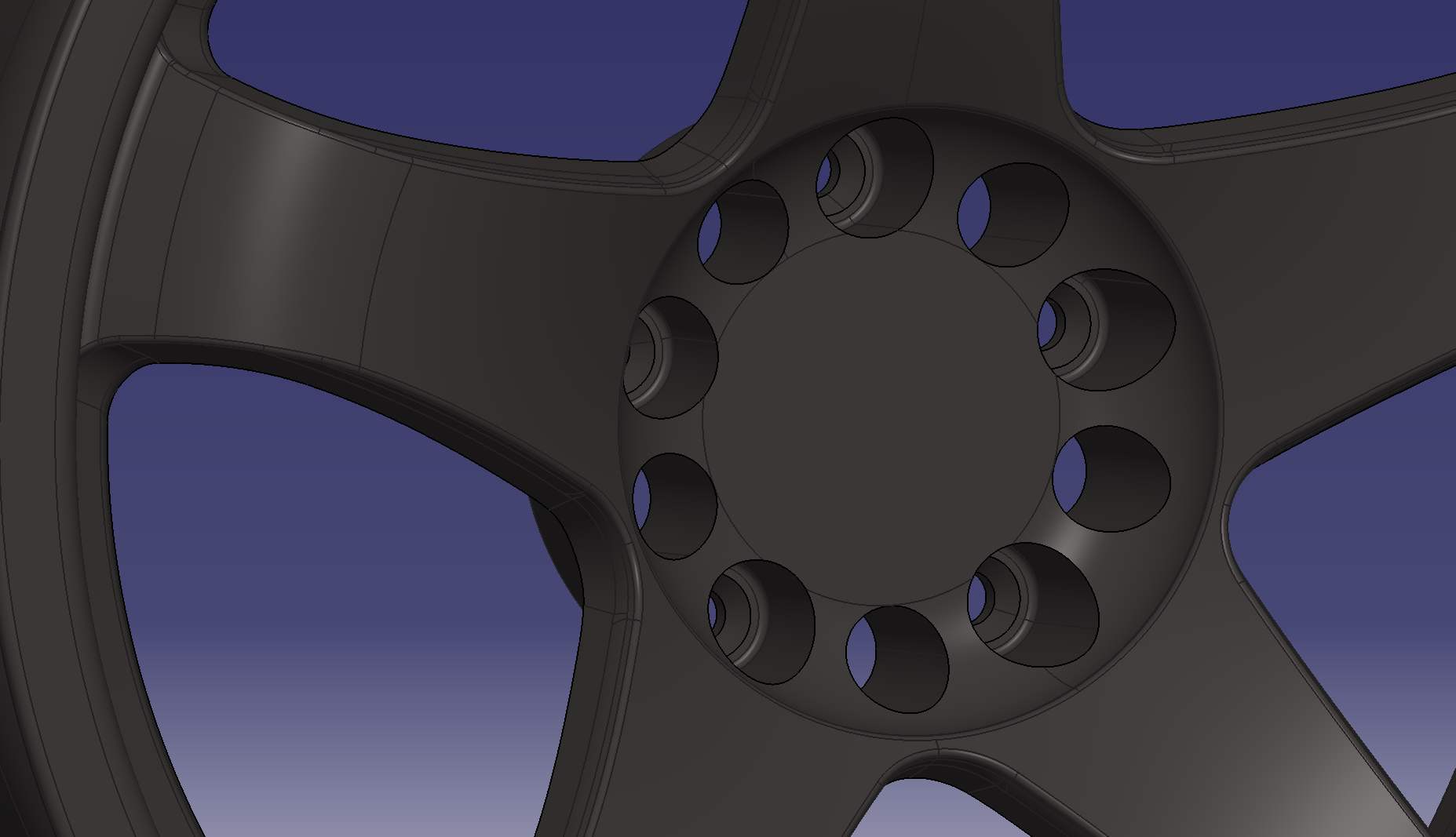
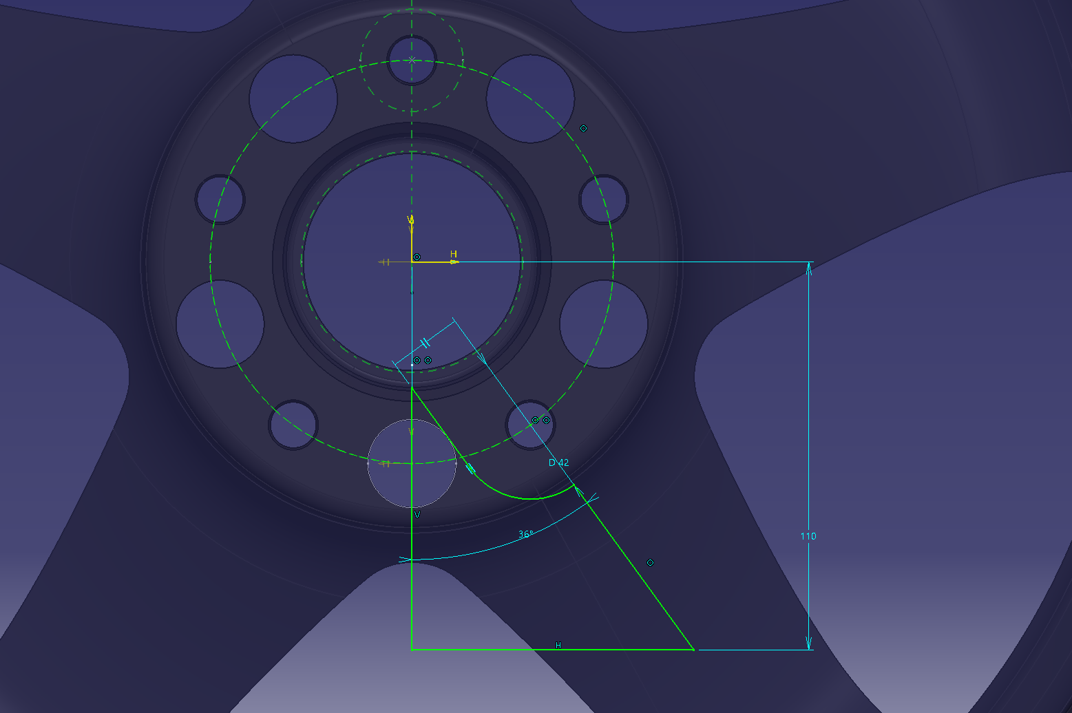
Make 8.5 holes
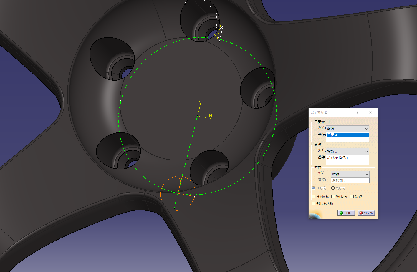
Sketch the dimensional criteria of the PCD on a plane with an offset surface of 15 mm on the wheel
PCD114.3
Set the origin to the point of the reference sketch in the placement sketch
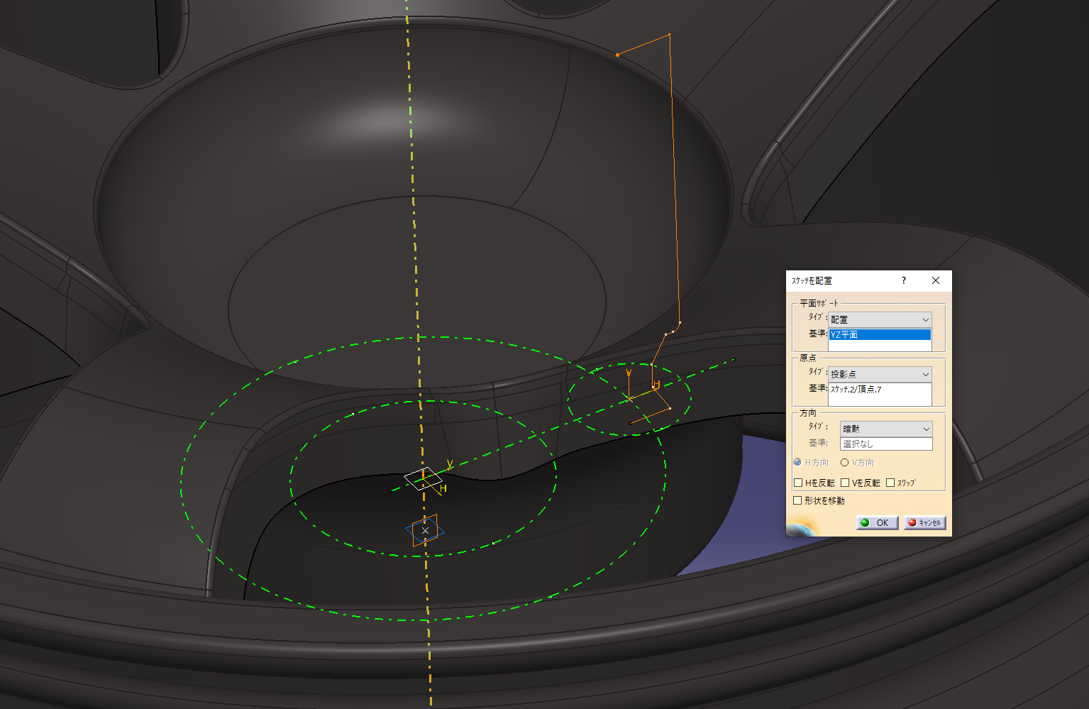
The same applies to the other hole shape. This makes a hole shape with a pad.
Sketch the axis center
9. Weight reduction on the back side
It feels like removing the meat except for the 5 holes.
Add fillets and then make a circular pattern
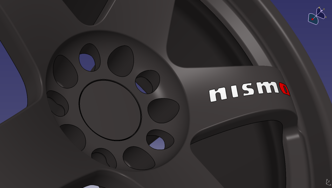
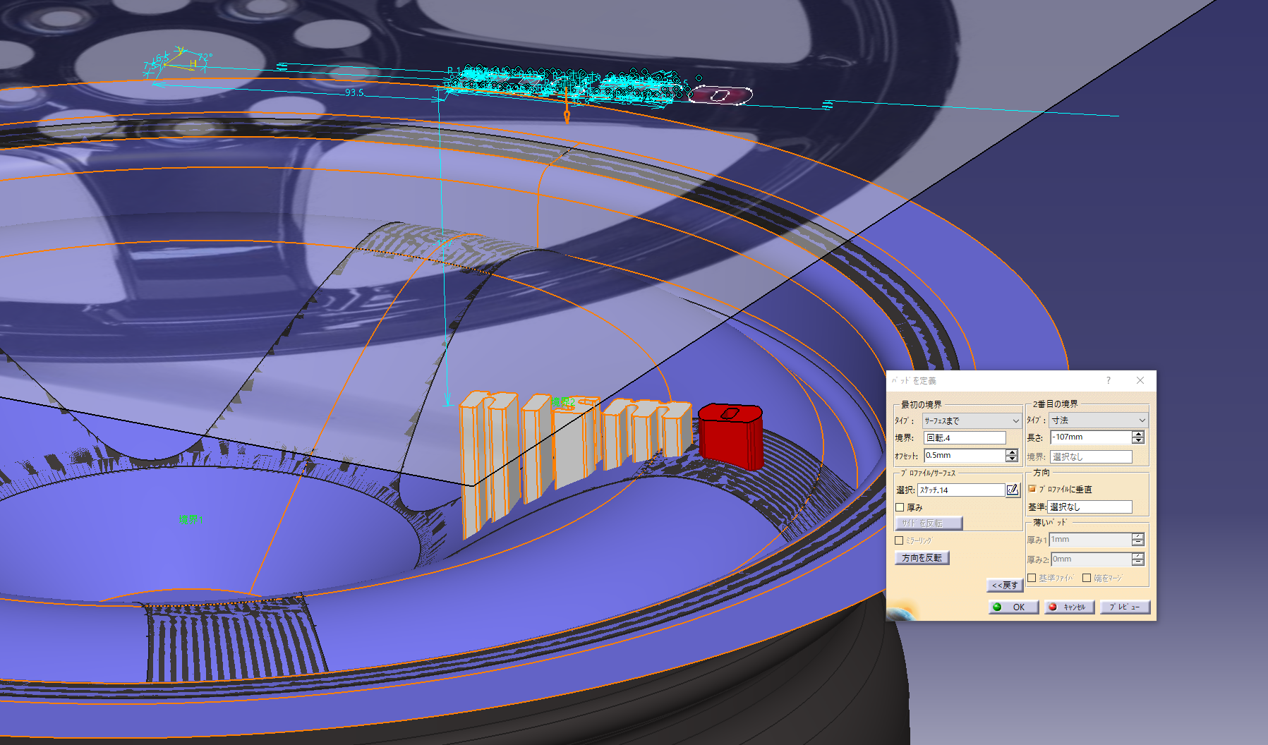
10. Engraved NISMO logo
Trace the NISMO logo with a sketch
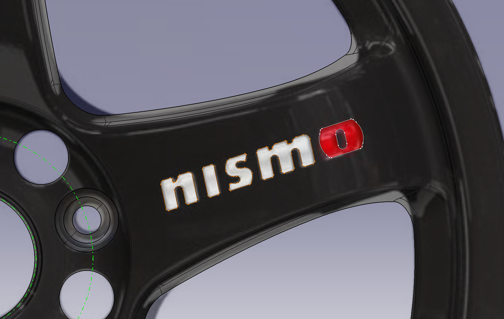
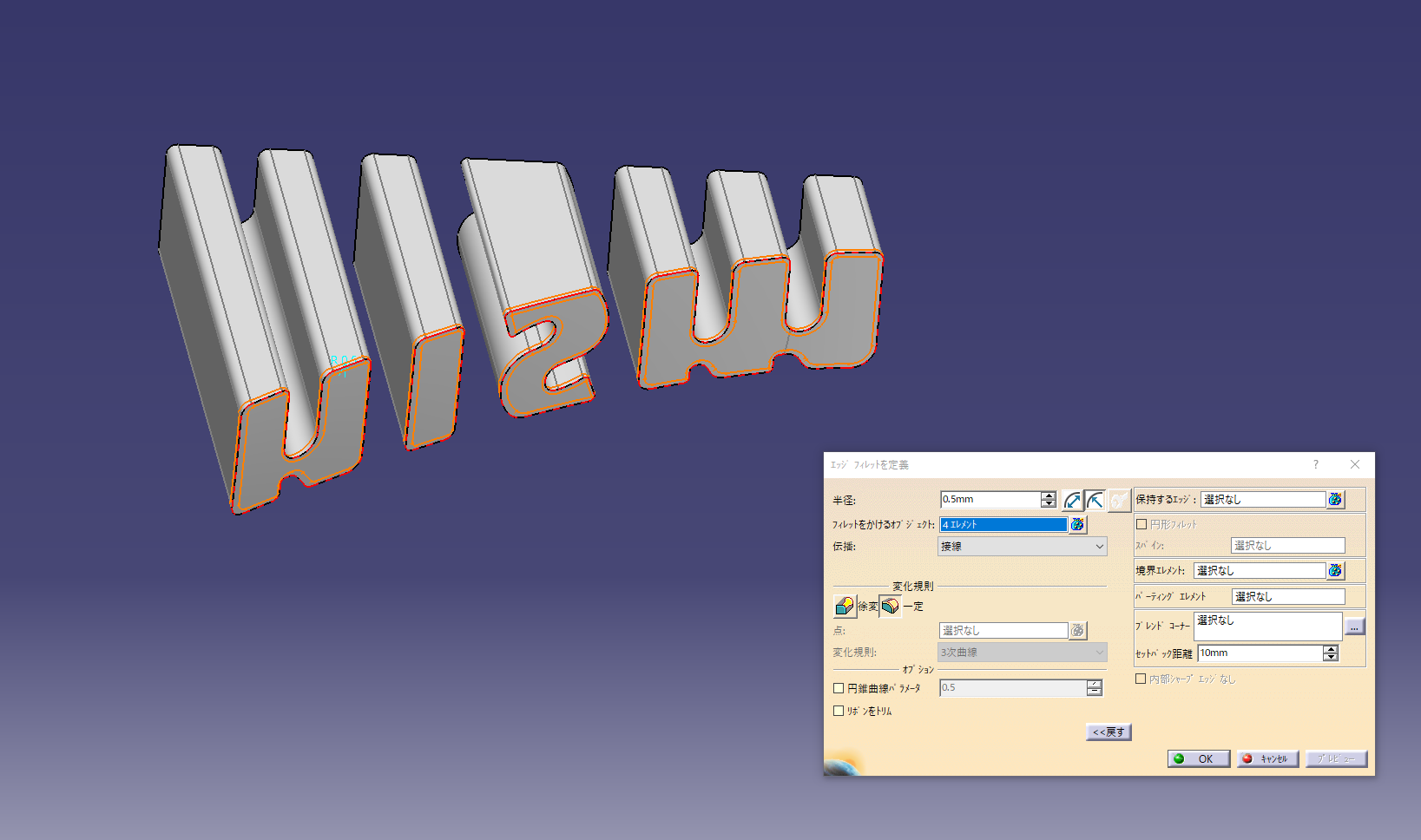
The face surface is specified as the boundary and the offset value is “engraved amount” (0.5 mm).
Add fillet
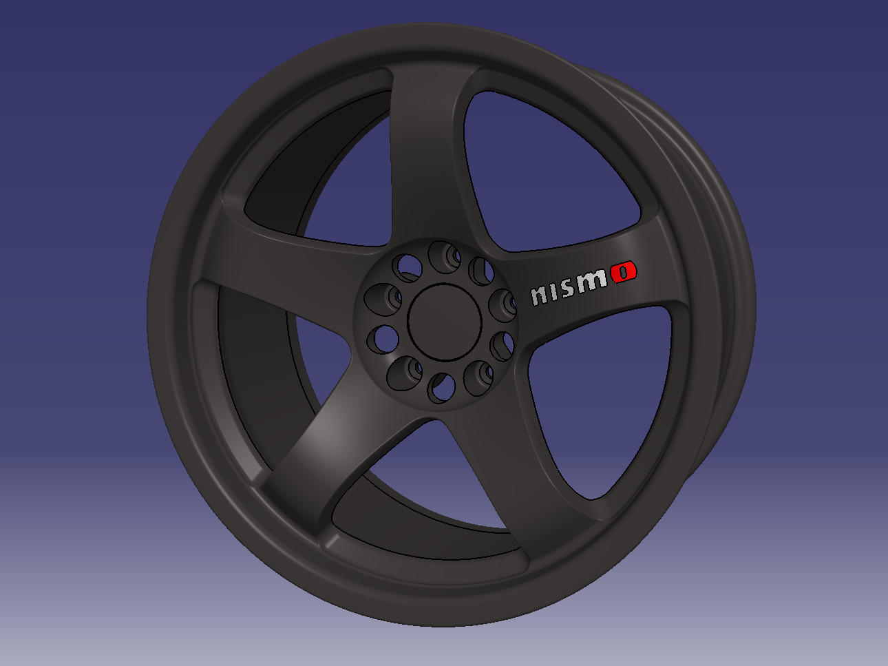
11. Completed Nismo-LMGT4
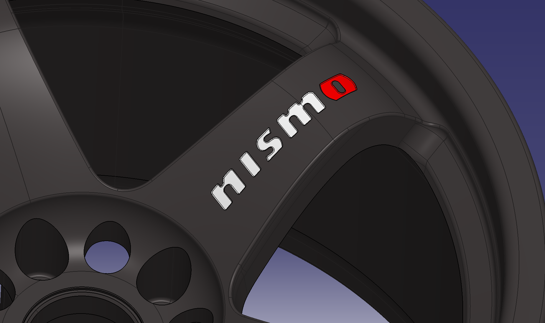
let’s make an original design